3
05.01
3.5 Overview, position sensing
3-67
Siemens AG 2001 All rights reserved
SIMODRIVE 611 Planning Guide (PJU) – 05.01 Edition
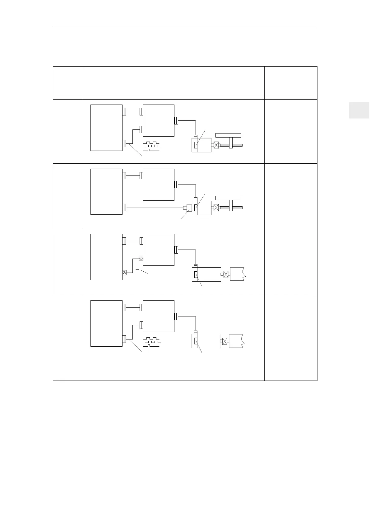
Table 3-2 Indirect position (motor rotor position) and motor speed sensing, analog controls
Control
board
Indirect position (motor rotor position)
and motor speed sensing, analog controls
M: Max. possible
measuring steps
G: Encoder system
accuracy
Z: Pulse number
Resolver
control
Numerical
control
SIMODRIVE
drive
module
(analog)
Positioning with NC
WSG interface
n*
l 50 m
Resolver
(incremental)
x4
1FK6
M = 1024 ⋅ 4
per 360 degrees
mech.
G = " 0.12 degrees
Feed
control
with
standard
and
user–friendly
interface
Numerical
control
SIMODRIVE
drive
module
(analog)
Positioning with NC
Optional encoder system
n*
1FT5
Tach. and RPS
l 150 m
M and G are
dependent on the
accuracy of the
optional encoder
system and the
evaluation technique
in the NC
Main
spindle
control
with analog
setpoint
interface
Numerical
control
SIMODRIVE
drive
module
(analog)
Spindle positioning with drive
!Positioning command!
n*
1PH4/6/7
Incremental
l 50 m
M = 2048 ⋅ Z
per 360 degrees
mech.
Z = 2048
G = " 0.006 degrees
Main
spindle
control
with analog
setpoint
interface
WSG
(angular
incremental e
output
for NC
Numerical
control
SIMODRIVE
drive
module
(analog)
Spindle positioning with the
NC
WSG interface
n*
1PH4/6/7
Incremental
l 50 m
M = k ⋅ Z ⋅ 4
per 360 degrees
mech.
Z = 2048
k...0.5, 1, 2, 4
(multiplication factor
which can be set in
the drive)
G = " 0.006 degrees
3 Motor Selection, Position/Speed Sensing

 Loading...


