3
05.01
3.5 Overview, position sensing
3-74
Siemens AG 2001 All rights reserved
SIMODRIVE 611 Planning Guide (PJU) – 05.01 Edition
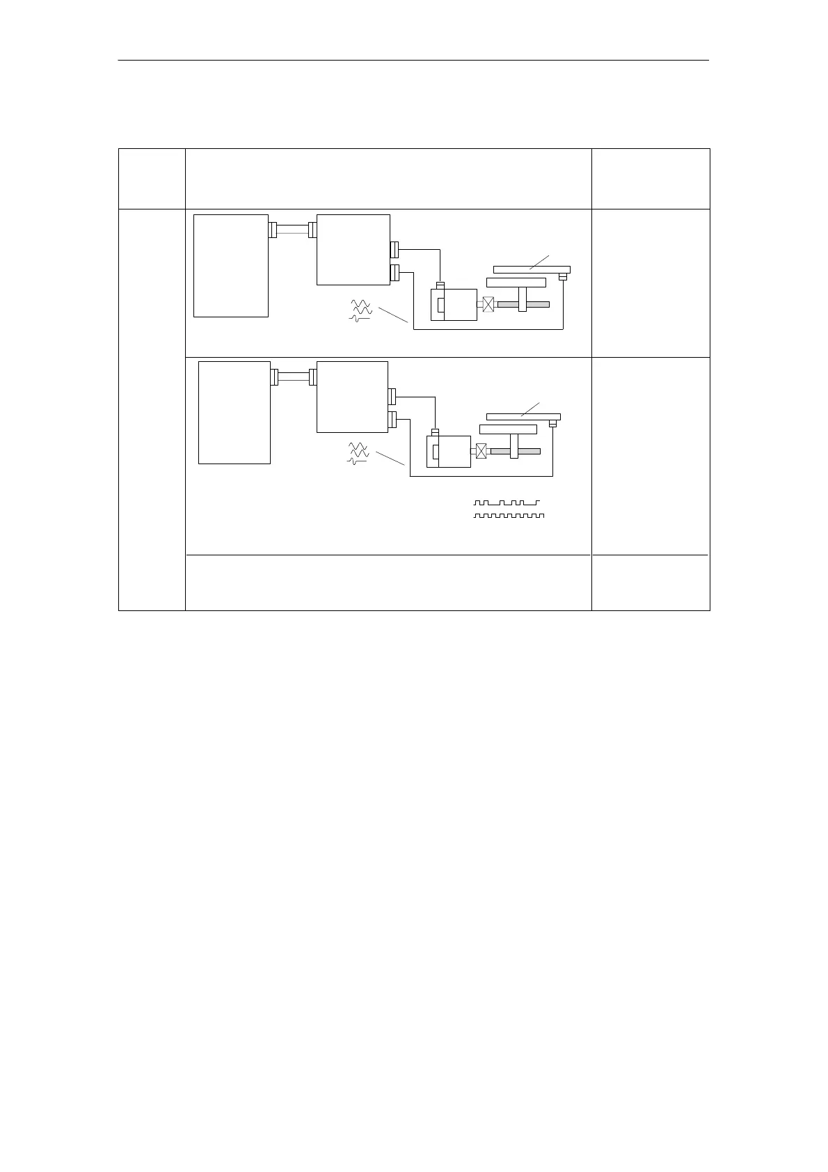
Table 3-5 Direct position sensing, digital controls
Control
board
version
Direct position sensing, digital controls
M: Max. possible
measuring steps
G: Encoder system
accuracy
Drive
control
Standard
SIMODRIVE
drive
module
Positioning with NC
n*
1FT6
Linear
2)
measuring system,
incremental
SINUMERIK
with digital
coupling
(digital)
Voltage signals
l 25 m
l 25 m
1FK6
M = 2048 per
encoder signal
period and grid
division
G is dependent on
the accuracy of the
optional encoder
system.
Digital
FD with
addi–
tional
input
voltage
signal
1FK6
SIMODRIVE
drive
module
Positioning with NC
n*
1FT6
Linear measuring
system, incremental
and absolute
SINUMERIK
with digital
coupling
(digital)
Voltage signals
and EnDat interface
Data
Clock
l 25 m
l 25 m
Note:
It is not possible to convert current signals into voltage signals via an SVE
(signal amplification electronics) due to the encoder power supply design!
3)
M, G=function of
the optional
encoder system
accuracy, the
evaluation
technique in the NC
and the mechanical
design. The
resolution per
encoder period and
grid division in the
drive is 128.
1) The absolute accuracy when synchronizing with a BERO is a function of:
– the BERO switching time
– BERO hysteresis
– signal edge gradient of the BERO signal (dependent on the direction of rotation!) and the switching thresholds
in the drive; high >13 V, low < 5 V
– the search speed or the signal run times in the evaluation electronics
2) Distance–coded reference marks can be evaluated when used as direct measuring system.
3) 25m cable: 6FX2002–2EQ10–1VVV
18m cable: 6FX2002–2EQ00–1VVV
3 Motor Selection, Position/Speed Sensing

 Loading...


