Operating range factor of control supply voltage 0.7 ... 1.1
Current-carrying capacity of the output relay
•
At DC-13 at 24 V
2 A
More information
For more inf
ormation about cable requirements, see Section "Cables and connectors
(Page130)".
For more information about assembling cable terminals, see Section "Assembling cables
(Page879)".
6.5.4 Connecting the encoder
6.5.4.1 Interface description - X120 (converter side)
Overview
The servo drive system supports three types of encoders:
• Absolute encoder, 17-bit single-turn
• Absolute encoder, 21-bit single-turn
• Absolute encoder, 21-bit single-turn +12-bit multiturn
The converter connects to the encoder of the motor on the interface X120.
Description
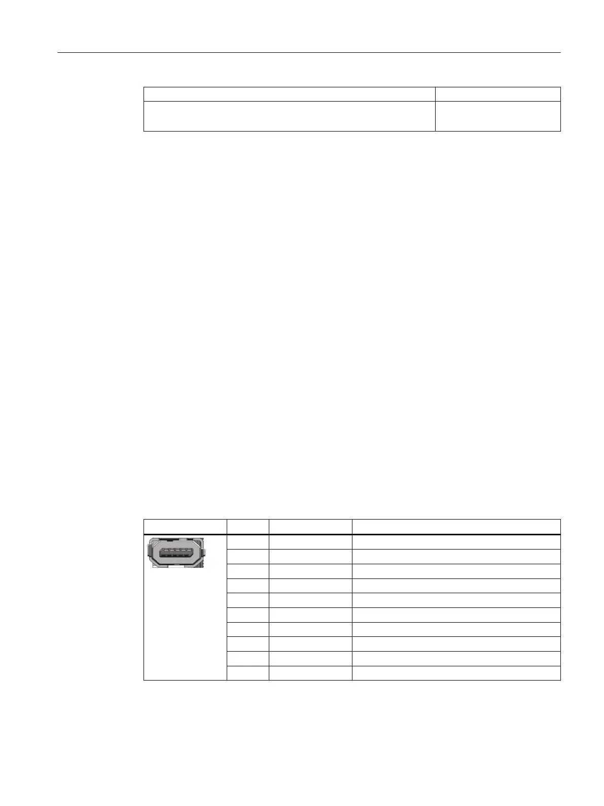
Table 6-6 Interface X120
X120 Pin Designation Technical specications
IX-C socket
1 DP1 Absolute encoder data signal, positive
2 DN1 Absolute encoder data signal, negative
3 Reserved Reserved
4 CLKP1 Absolute encoder clock signal, positive
5 CLKN1 Absolute encoder clock signal, negative
6 M Reference ground
7 Power_ENC1 Encoder power supply, 5V DC
8 M_ENC1 Encoder power supply, reference ground
9 Reserved Reserved
10 Reserved Reserved
Connecting
6.5Connecting the motor
SINAMICS S200 PROFINET servo drive system with SIMOTICS S-1FL2
Operating Instructions, 11/2023, FW V6.3, A5E51646752B AB 143