6.8 Connecting the inputs and outputs
6.8.1 Inter
face description - X130
Overview
The converter connects to the controller for signal transmission on the interface X130.
Description
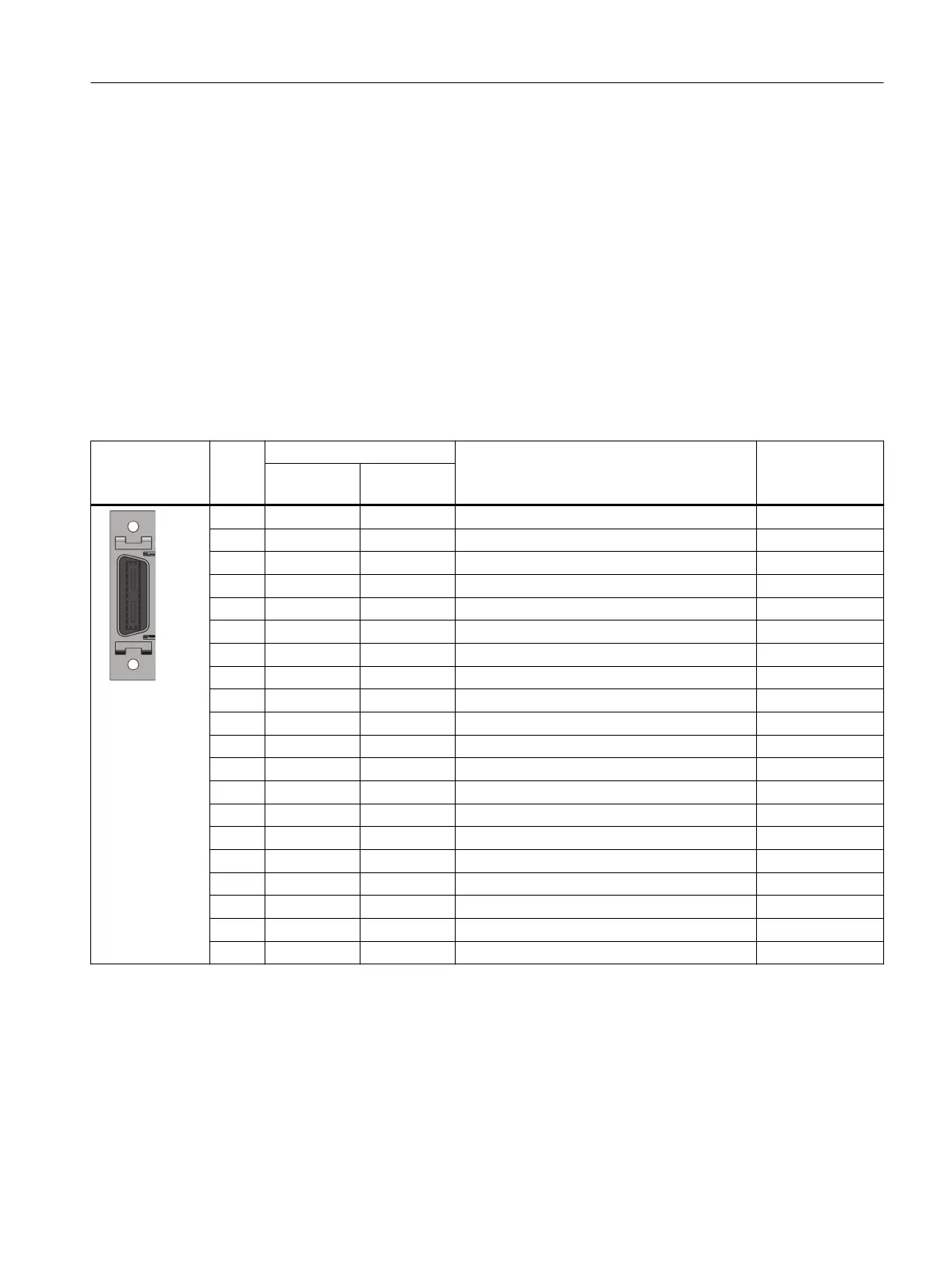
Table 6-11 Interface X130
X130 Pin Designation Technical specications Conductor color
S200 PN S200 Basic
PN
20-pin MDR
soc
k
e
t
Tightening tor‐
que: 0.2Nm
1 DI0 DI0 Digital input 0 (high-speed digital input) White-Gray
2 DI1 DI1 Digital input 1 (high-speed digital input) Gray-Brown
3 DI2 DI2 Digital input 2 White-Pink
4 DI3 DI3 Digital input 3 Pink-Brown
5 M M Reference ground White
6 DI_COM DI_COM Common terminal for digital inputs Brown
7 DI_COM DI_COM Common terminal for digital inputs Green
8 M M Reference ground Yellow
9 - - - -
10 FE FE Functional grounding Pink
11 DO0+ DO0+ Digital output 0, positive Blue
12 DO0- DO0- Digital output 0, negative Red
13 DO1+ - Digital output 1, positive Black
14 DO1- - Digital output 1, negative Violet
15 PTOA+ - Pulse train output A, positive Gray-Pink
16 PTOA- - Pulse train output A, negative Red-Blue
17 PTOB+ - Pulse train output B, positive White-Green
18 PTOB- - Pulse train output B, negative Brown-Green
19 PTOZ+ - Pulse train output Z, positive White-Yellow
20 PTOZ- - Pulse train output Z, negative Yellow-Brown
More information
For more inf
ormation about cable requirements, see Section "Cables and connectors
(Page130)".
For more information about assembling cable terminals, see Section "Assembling the I/O
connector (Page884)".
Connecting
6.8Connecting the inputs and outputs
SINAMICS S200 PROFINET servo drive system with SIMOTICS S-1FL2
Operating Instructions, 11/2023, FW V6.3, A5E51646752B AB 153