4.4 Line connection conditions for the converter with the motor 1FL2
Description
The dr
ive system is designed for connection to grounded TN/TT and non-grounded IT mains
supply networks.
Depending on the motor/converter combination and the planned installation altitude, the
following constraints must be taken into account regarding the line connection.
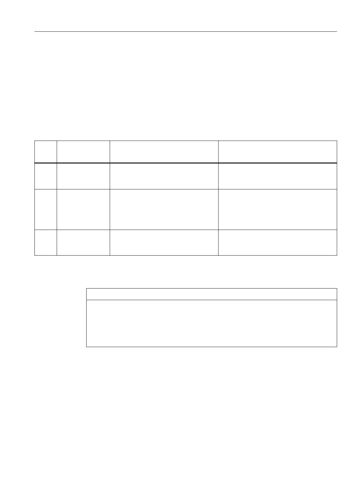
Table 4-2 Line connection conditions for the converter with the motor 1FL2
Motor Converter input
v
oltage
Permissible line system congurations
for installation altitude no higher
than2000 m
Permissible line system congurations for in‐
stallation between 2000 m and4000 m
200V 1 AC 200 V ... 240 V
(-15%...+10%)
• TN and TT line systems with grounding
at any pot
ential
• IT line systems
*)
Install an isolating transformer and ground the
secondary side at any potential.
200V 3 AC 200 V ... 240 V
(-15%...+10%)
• TN and TT line systems with grounding
at any pot
ential
• IT line systems
*)
• TN and TT line systems with grounded neu‐
tral point
• IT line systems with an isolating transformer
with grounded neutral point (secondary
side)
400V 3 AC 380 V ... 480 V
(-15%...+10%)
• TN and TT line systems with grounded
neutral point
• IT line sy
stems
*)
Install an isolating transformer and ground the
secondary side at the neutral point.
*)
With t
he IT screw for the functional grounding removed. For more information about
removing the IT screw, see Section "Removing the IT screw for the functional grounding
(Page84)".
NOTICE
Damage to motor insulation due to excessive voltages
In the
event of a ground fault in the IT supply system, the motor insulation can be damaged by
the higher voltage to ground.
• Use a ground fault monitor.
• Eliminate the ground fault as quickly as possible.
Application planning
4.4Line connection conditions for the converter with the motor 1FL2
SINAMICS S200 PROFINET servo drive system with SIMOTICS S-1FL2
Operating Instructions, 11/2023, FW V6.3, A5E51646752B AB 83