6.6 Connecting the braking resistor
6.6.1 Inter
face description - X1
Overview
The converter connects to the braking resistor via terminals DCP, R1, and R2 on the interface X1.
Description
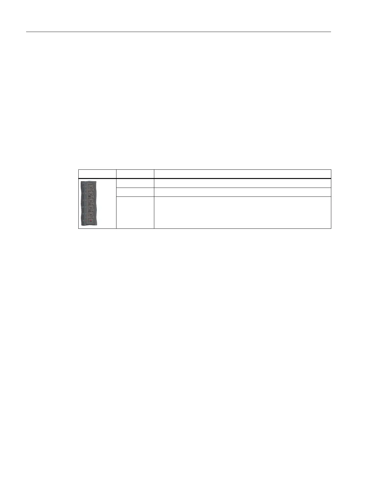
Table 6-9 Interface X1
X1 Terminal Designation
DCP DC link positive (for connection to the braking resistor)
R2 Connection to the internal braking resistor
1)
R1 Connection to the external braking resistor
1)
S200 Basic PN (FSA and FSB) and S200 PN FSA (0.1kW) do no
t have an internal braking resistor.
6.6.2 Wiring
Overview
S200 Basic PN FSC and S200 PN (excluding FSA 0.1 kW) converters have an integrated braking
resistor for absorbing regenerative energy from the motor. To use the internal braking resistor,
connect DCP and R2 with the jumper included in the scope of delivery.
To use an external braking resistor, connect the converter to an external braking resistor via
terminals DCP and R1.
When the terminal R1 or R2 is not in use, cover it with the blanking plug provided in the
connector kit (installed on R1 upon delivery).
Connecting
6.6Connecting the braking resistor
SINAMICS S200 PROFINET servo drive system with SIMOTICS S-1FL2
148 Operating Instructions, 11/2023, FW V6.3, A5E51646752B AB