Requirement
WARNING
Electric shock as a result of a residual charge in power components
After
the power supply has been switched o, it takes up to ve minutes until the capacitors in
the converter have discharged so that the residual charge is at a non-hazardous level. Touching
the converter immediately after powering o can result in electric shock due to residual charge
in the power components.
• Check the voltage at the converter connections before you connect the external braking
resistor.
WARNING
Fire caused by an unsuitable or improperly installed braking resistor
Using an unsuit
able or improperly installed braking resistor can result in re and formation of
smoke. Fire and smoke can cause severe personal injury or property damage.
• Only use braking resistors that are approved for the converter.
• Install the braking resistor in accordance with regulations.
Procedure
Connecting the internal br
aking resistor
1. Switch o all power supplies to the converter, including the mains supply and the 24 V DC
power supply.
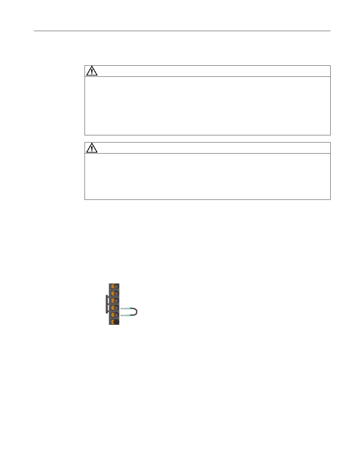
2. Cover the terminal R1 with the blanking plug.
3. Connect DCP and R2 with the jumper included in the scope of delivery as shown below:
Connecting an external braking resistor
1. Switc
h o all power supplies to the converter, including the mains supply and the 24 V DC
power supply.
2. Wait for ve minutes to allow the converter to discharge and check that no voltage is present
at the converter connections.
3. Remove the connection between DCP and R2.
Connecting
6.6Connecting the braking resistor
SINAMICS S200 PROFINET servo drive system with SIMOTICS S-1FL2
Operating Instructions, 11/2023, FW V6.3, A5E51646752B AB 149