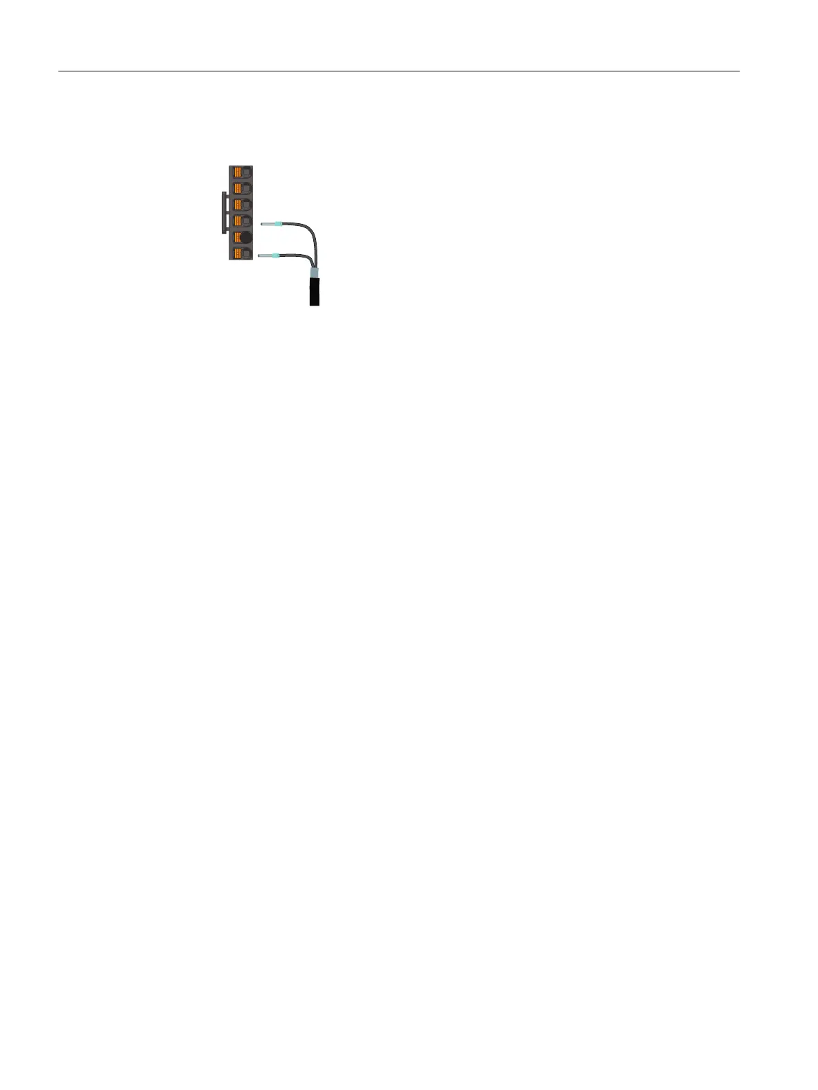
4. Remove the blanking plug from R1 and insert it into R2.
5. Connect t
he external braking resistor cable to terminals DCP and R1 as shown below:
More information
For more inf
ormation about cable requirements, see Section "Cables and connectors
(Page130)".
For more information about assembling cable terminals, see Section "Assembling cables
(Page879)".
Connecting
6.6Connecting the braking resistor
SINAMICS S200 PROFINET servo drive system with SIMOTICS S-1FL2
150 Operating Instructions, 11/2023, FW V6.3, A5E51646752B AB