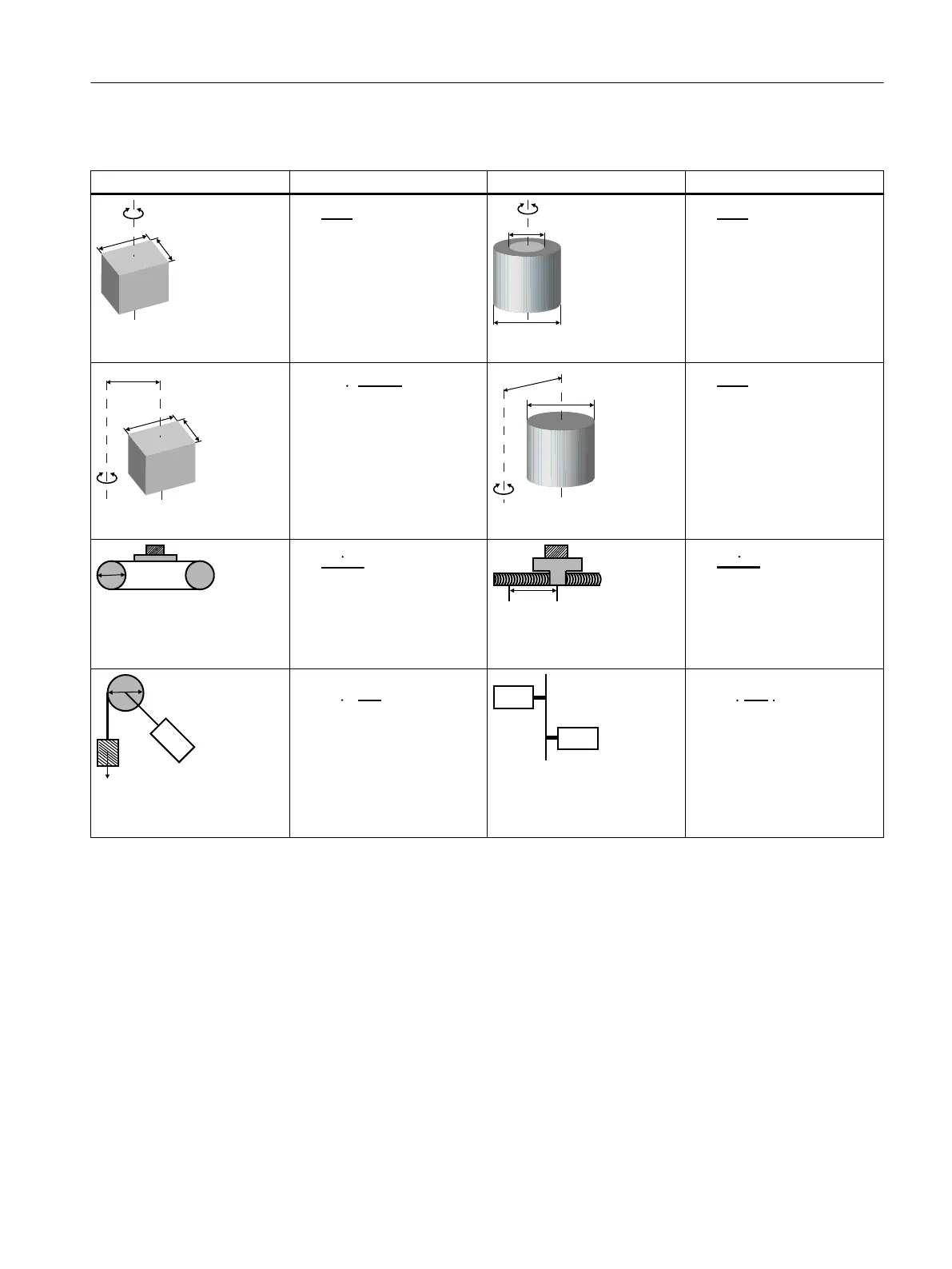
Typical load inertia equations
Mechanism Equation Mechanism Equation
Axis of rotation on center
W: Mass (kg)
a: Length (m)
b: Widt
h (m)
Axis of rotation on center
W: Mass (kg)
D
1
: External diamet
er (m)
D
2
: Internal diameter (m)
Axis of rotation o cent
er
W: Mass (kg)
a: Length (m)
b: Widt
h (m)
R: Rotational diameter (m)
Axis of rotation o center
W: Mass (kg)
D: Workpiece diame
ter (m)
R: Rotational diameter (m)
Conveyor
W: Mass (kg)
D: Pulley wheel diamet
er (m)
Ball screw
W: Mass (kg)
P: Lead (m)
J
b
: Ball screw iner
tia (kg·m
2
)
Object hung with pulley
W: Mass (kg)
D: Pulley wheel diamet
er (m)
J
p
: Pulley inertia (kg·m
2
)
Reducer
W: Mass (kg)
n
1
/n
2
: Speed of each mot
or
(rpm)
J
1
/J
2
: Inertia of each motor
(kg·m
2
)
A.5.2 Selection examples
Descr
ip
tion
This section uses a ball scr
ew mechanism as an example to illustrate the motor selection
procedure.
Exemplary data
The following table lists the data related to the ball screw mechanism and operation pattern.
Workpiece weight W 40 kg
Material density of the ball screw ρ 7.9 × 10
3
kg/m
3
Appendix
A.5Motor selection
SINAMICS S200 PROFINET servo drive system with SIMOTICS S-1FL2
Operating Instructions, 11/2023, FW V6.3, A5E51646752B AB 901