Mounting and Commissioning
3.1 Mounting and Connections
SIPROTEC, 7UM62, Manual
C53000-G1176-C149-7, Release date 03.2010
385
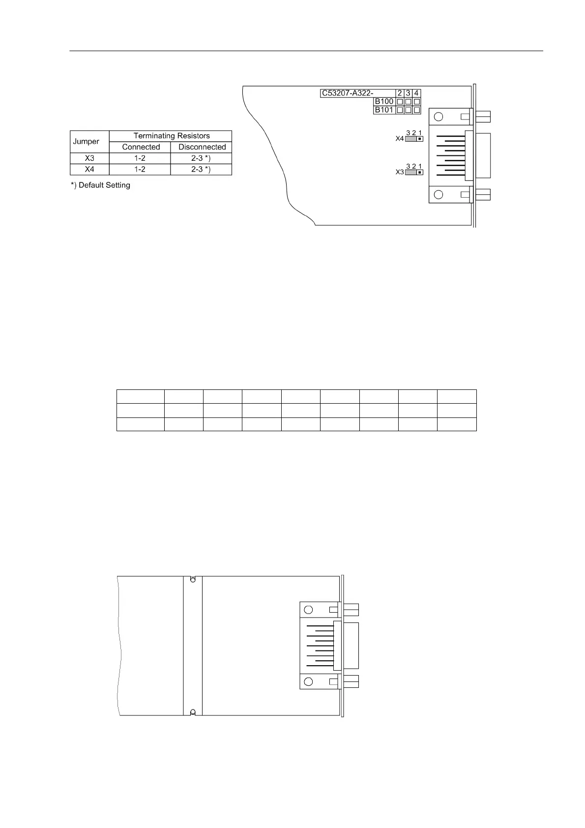
Figure 3-11 Position of the plug-in jumpers for the configuration of the terminating resistors at the Profibus
(FMS and DP), DNP 3.0 and Modbus interfaces
The terminating resistors can also be connected externally (e.g. to the terminal block), see Figure 3-4. In this
case, the terminating resistors located on the RS485 or PROFIBUS interface module or directly on the PCB of
the C-CPU-2 board of must be disabled.
It is possible to convert the R485 interface to a RS232 interface by changing the jumper positions and vice-
versa.
Jumper positions for the alternatives RS232 or RS485 (as in Figure 3-10) are derived from the following Table.
Table 3-23 Configuration for RS232 or RS485 on the interface module
The jumpers X5 to X10 must be plugged in the same way!
The jumpers are preset at the factory according to the configuration ordered.
Analog Output
The AN20 analog output interface module (see Figure 3-12) has 2 floating channels with a current range of 0
to 20 mA (unipolar, max. 350 Ω).
The location on the C–CPU-2 board is „B“ or/and „D“ depending on the variant ordered (see Figure 3-9).
Figure 3-12 AN20 analog output interface board
Jumper X5 X6 X7 X8 X10 X11 X12 X13
RS232 1-2 1-2 1-2 1-2 1-2 2-3 1-2 1-2
RS 485 2-3 2-3 2-3 2-3 2-3 2-3 1-2 1-2

 Loading...


