Mounting and Commissioning
3.1 Mounting and Connections
SIPROTEC, 7UM62, Manual
C53000-G1176-C149-7, Release date 03.2010
384
Table 3-22 Replacing interface modules
The order numbers of the replacement modules can be found in the Appendix in Section A.1.
EN100 Ethernet Module (IEC 61850)
The Ethernet interface module has no jumpers. No hardware modifications are required to use it.
Termination
For bus-capable interfaces, a termination is necessary at the bus for each last device, i.e. terminating resistors
must be connected. With the 7UM62 device, this concerns the variants with RS485 or PROFIBUS interfaces.
The terminating resistors are located on the RS485 or Profibus interface module, which is on the C–CPU-2
board ((1) in Figures 3-1 and 3-2), or directly on the PCB of the C-CPU-2 board (see margin title „C-CPU-2
Processor Board“, Table 3-2).
Figure 3-9 shows the PCB of the C-CPU-2 with the layout of the boards.
The module for the RS485 interface is shown in Figure 3-10, the module for the Profibus interface in Figure 3-
11.
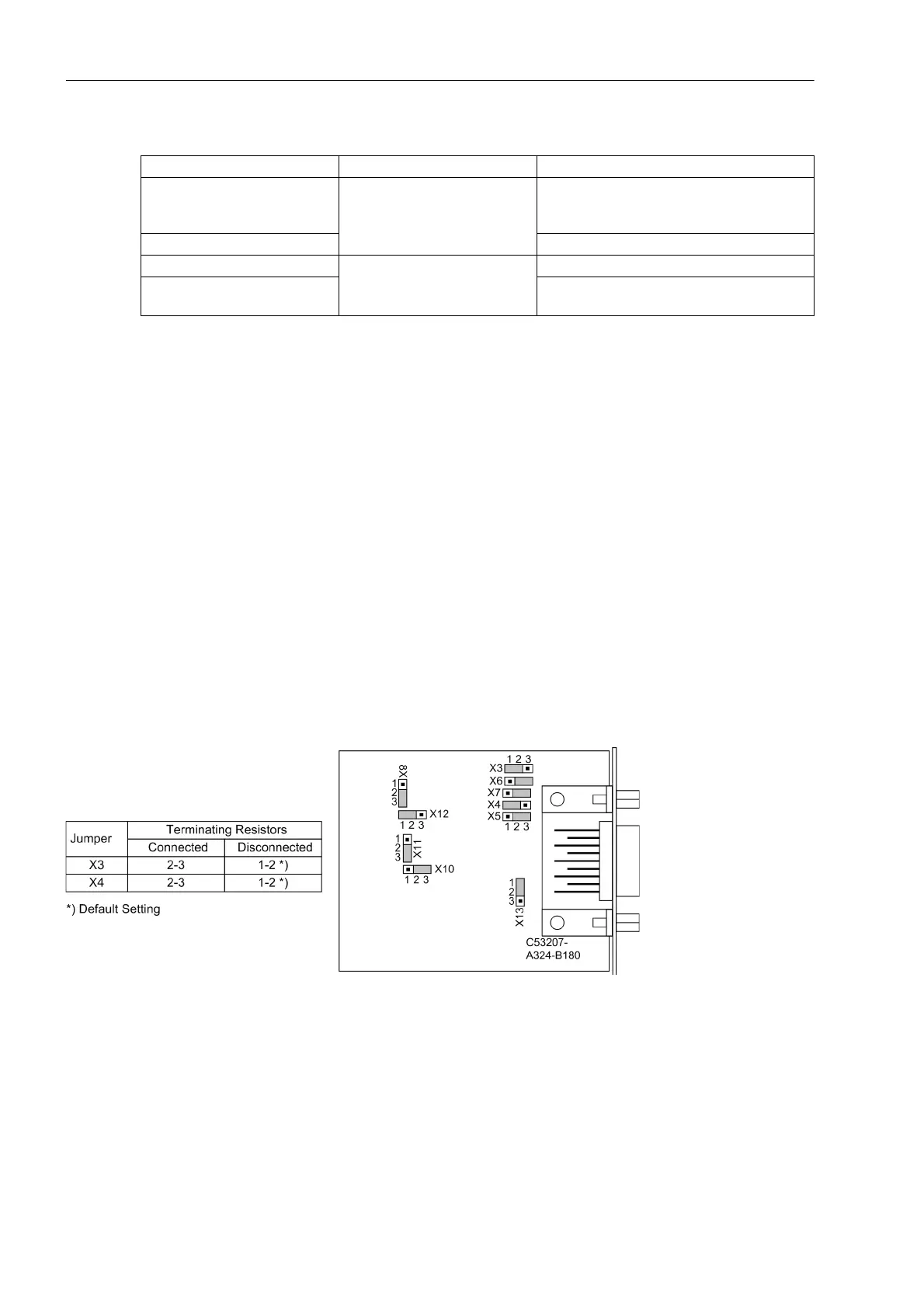
On delivery, the jumpers are set so that the terminating resistors are disconnected. Both jumpers of a module
must always be plugged in the same way.
Figure 3-10 Position of terminating resistors and the plug-in jumpers for configuration of the RS485 interface
Interface Mounting Location / Interface Replacement module
System interface
B
Only interface modules that can be ordered
in our facilities via the order key (see Appen-
dix, Section A.1).
Analog Output 2 x 0 to 20 mA or 4 to 20 mA
Analog Output
D
2 x 0 to 20 mA or 4 to 20 mA
RTD-box
RS485
FO

 Loading...


