Section 7
7.1
COMMUNICATION
Introduction
The data to be sent and/or received, as well as the order that it will be in the communication bus, are
defined by the user through the configuration of the CD600 Plus communication blocks (blocks 119,
120 and 121).
These blocks should be placed in the configuration’s loop G, and each one has a specific function:
- BLK119 (SCAN) – It is used to place the desired data in the communication bus. Data such as
analog and/or digital outputs of any block of the configuration can be read as well as configuration,
limits and alarm statuses, inputs, L/R and A/M switch status and totalizations.
- BLK 120 (PID) – The gain values (K
P
), integral time (T
R
), derivative time (T
D
) and the Bias (B), of
the PID blocks of the controller, can be read and changed through the communication, with the use
of this block in the configuration.
- BLK 121 (ACTUATION) – Used to act in the controller’s commands, such as, L/R and A/M
transferences; change values such as SP, manual output and internal registers of the controller;
changes in the alarm limits and alarm generation through analog variables and discrete signals for
the controller.
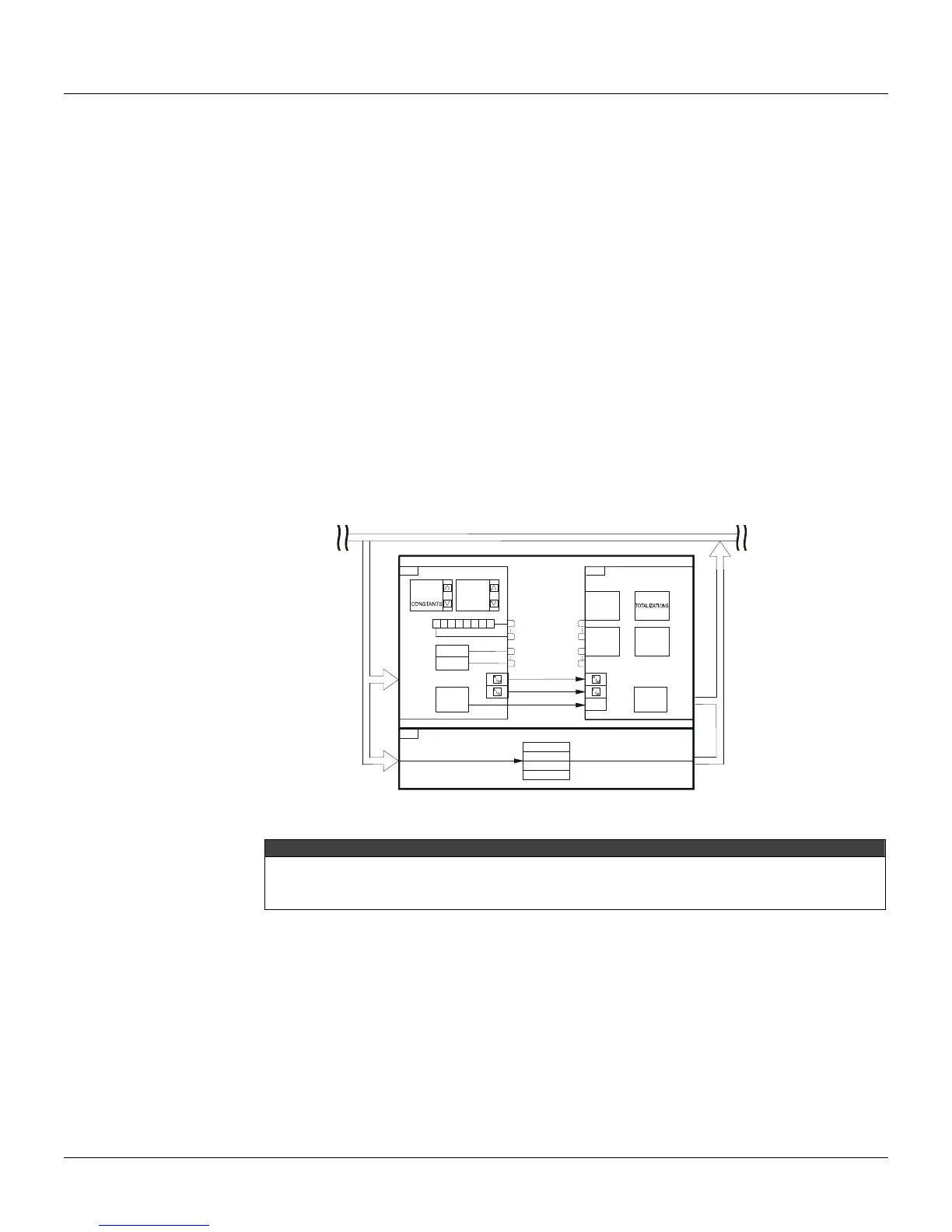
Fig. 7.1 shows the information exchange between the MASTER (the supervisory, for example) and
the SLAVE, that is, the controller on the bus.
BUS
CD 600
120 PID
168
169
170
KP
TR
TD
B
161
(32)
(8)
119
ANALOG
BLOCK
OUTPUTS
DIGITAL
BLOCK
OUTPUTS
DIGITAL
INPUTS AND
OUTPUTS
ALARM
LIMITS
121
ACTUATION
SETPOINT OUTPUT
MANUAL
WORD 1
WORD 2
ALARM
LIMITS
Fig 7.1 Block Communication Diagram
NOTE
In order for the MASTER to communicate with a network controller, it is necessary that on this configuration,
the three communication blocks (BLK 119, 120 and 121) are present, even if any of these blocks does not
contain necessary information for the communication.
Controller Address
The CD600 Plus has a serial communication channel in the EIA-485-A standard and function blocks
in the software that allow the implementation of a <Master-Slave> communication.
The controllers should be connected in a multi-drop, in parallel, with a maximum number of 29
controllers per channel. Each controller on the network should have a specific address, in order to
allow access by the MASTER. The procedure to address a controller is as described:
a) Hold the <ACK> key in front of the display, until the display changes.
b) Press <ACK> and <DSP> together, and the display will show the ID address of the CD600 Plus. In
this point the display will be showing: