Section 8
8.1
TECHNICAL SPECIFICATIONS
Power Supply and Consumption
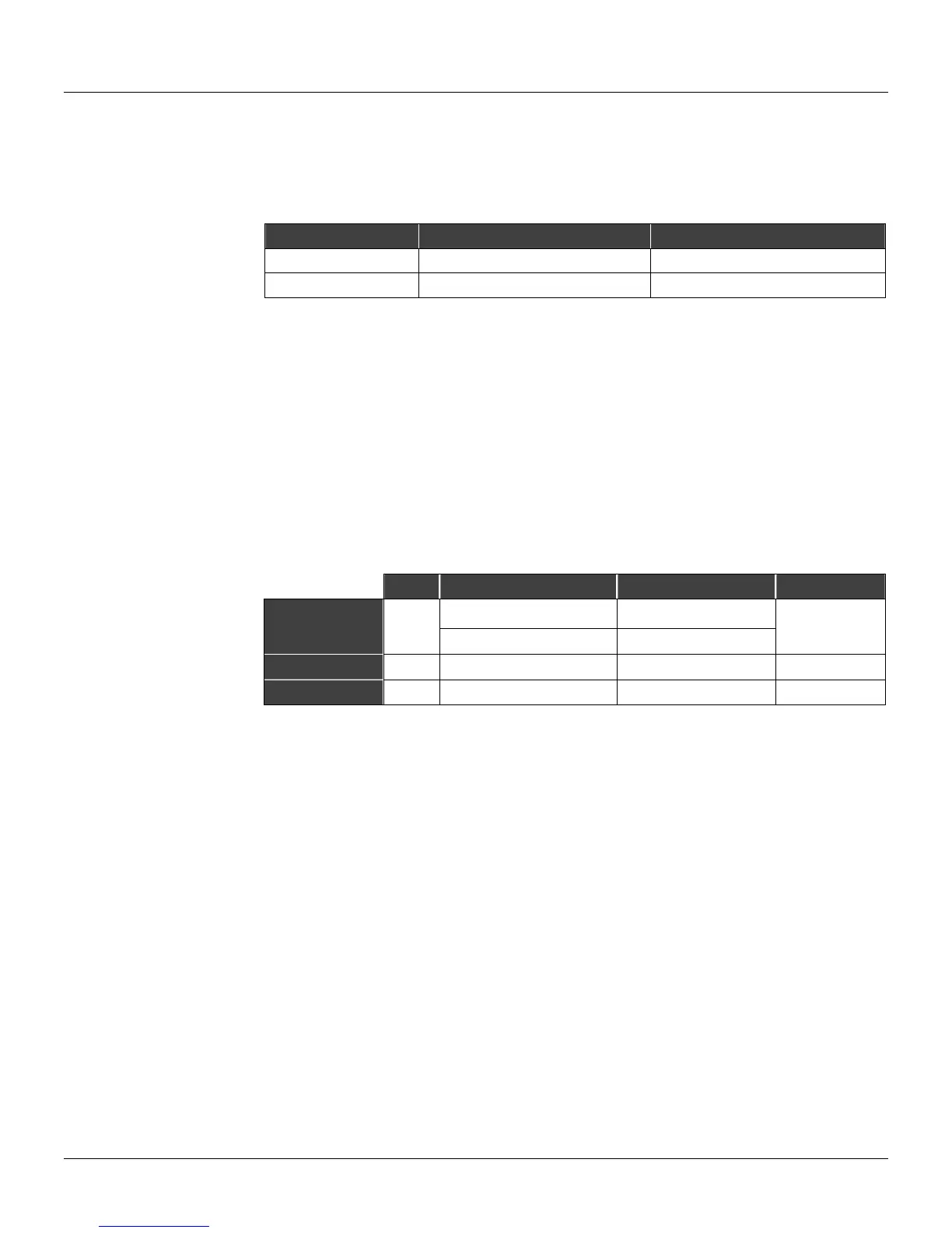
The table below specifies the maximum current values.
MODEL SUPPLY VOLTAGE CONSUMPTION
CD600plus A 85-264 Vac 50-60 Hz 16 VA @ 110 Vac / 10VA
CD600plus-D 20-30 Vdc 22.7 W @ 24 Vdc / 23 W @30 Vdc
Table 8.1. Power Consumption
Integral Power Supply for Transmitters
- Regulated Output Voltage: 24 V ±10%
- Maximum Output Current: 200 mA
- Short-circuit current limitation
NVRAM (Non-volatile RAM)
The data is stored in the memory built in battery. It is a non-rechargeable battery, made of Lithium,
and in normal operation lasts up to 10 years of data storage.
Analog Inputs and Outputs
Q TYPE LOAD/IMPEDANCE ACCURACY
4-20 mA / 0-20 mA
(1)
250 Ω
Analog input
8
1-5 V / 0-5 V
1 MΩ
± 0.010 V
Current Output
4 4-20 mA / 0-20 mA
(2)
Max. 750 Ω ± 0.050 mA
Voltage Output
4 1-5 V / 0-5 V
Min. 1.5 KΩ ± 0.015 V
(3)
NOTES:
(1) To change the current input to voltage input and vice-versa, it is necessary to remove or insert a
250 Ohm shunt resistor placed behind the panel, between the terminal bars. The position of
each shunt is marked with the corresponding input number.
(2) For each tim cycle < 200 ms; the accuracy will be: 0.020V.
Digital Inputs (DI1 to DI8)
Quantity: 08
Type: Voltage or relay contact
Frequency: 0 to 10 KHz (DI1 to DI2)
Accuracy: 0.05% (10 Hz < f < 10 KHz)
0.3% (1 Hz ≤ f ≤ 10 Hz)
Isolation: Optical – 5kV
Auxiliary Voltage Vext: 20-30 Vdc
Recognition of Low Logic Level "0": Closed contact with a 200Ω resistance maximum or 0 to 1.7
Vdc
Recognition of high Logic Level "1": Open contact with a 50 KΩ resistance minimum or 3 to 24
Vdc
NOTE: A "Debouncing Circuit" is necessary when a pulse input is connected to a relay
(electromechanical switch). The mechanic switch will not generate an instant reset, but the
millisecond oscillation caused by the input signal may cause a mis-interpretation of the relay status.