Section 16
COMMUNICATION
The data to be sent or received by the CD600 Plus is defined by the communication blocks
BLK119, BLK120 and BLK121.
These blocks should be allocated in the Loop G of the configuration, each one with a specific
function:
• BLK119 (SCAN) - All data required by the communication bus are available in this block. The
block contains: analog and/or digital outputs from any functional block used in a configuration,
alarm limits and status, digital inputs and outputs, status of L/R and A/M selectors and
totalizations.
• BLK120 (PID) - The values of Proportional Gain (KP), Integral Time Constant (TR), Derivative
Time (TD) and Bias (B) of the PID Controller blocks can be read and changed by the
communication bus with this block.
• BLK121 (ACTUATION) - This block is used to actuate the controller's commands, such as L/R
and A/M selectors and to change values such as SP, manual output and registers of the
controller. It changes the alarm limits and generation of analog and discrete variables.
Checking the controller
To check the CD600 Plus identification address:
1. Press the <ACK> key at the front panel of the CD600 Plus and hold for a few seconds until the
display message changes.
2. Press the <ACK> and the <DSP> keys together, the display will show the Identification Address
of the CD600 Plus.
3. Use the keys <Δ> and <∇> on the front panel of the controller to change the numerical value of the
display. The value “1” means that the controller accepts the communication with the PDA only.
Values from “2” and “30” are the programmed controller addresses in the serial communication
network.
4. Click the <LP> key to return to normal operation.
Configuring the communication
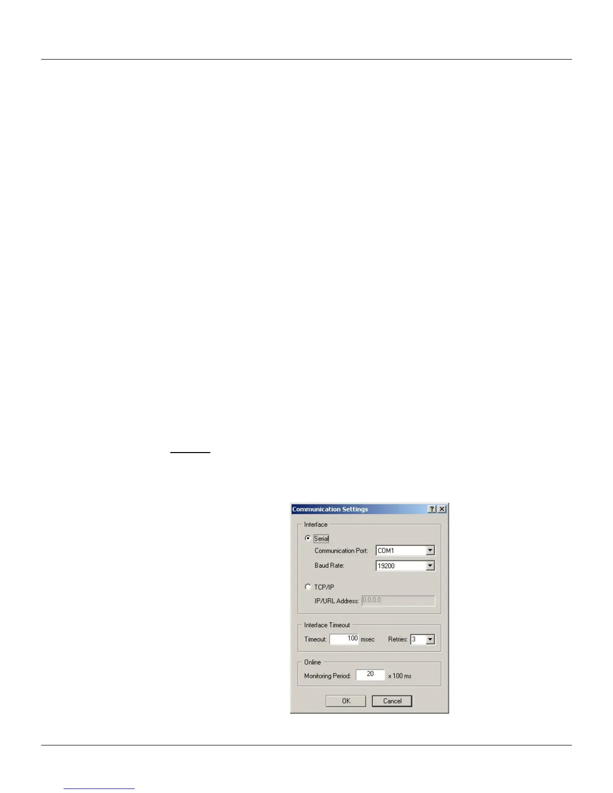
To configure the communication, go to the Tool menu and click Comm Settings. The
Communication Settings dialog box will open:
Shortcut:
Keyboard: F10
To configure the remote communication via Ethernet, it will be necessary to configure the serial port
of the ENET-710 module. Refer to the ENET-710 User’s Manual for further information to configure
the module.
Figure 16.1 - Communication Settings Dialog Box
16.1