Section 17
17.1
CALIBRATION
The CD600 Plus is factory calibrated according to procedures complying with the ISO9000
Standards. If a new calibration is required, it can be easily done through the CONF600 Plus.
First, check the CD600 Plus identification address. Press the <ACK> key at the front panel of the
CD600 Plus and hold for a few seconds until the display message changes. Then press the <ACK>
and the <DSP> keys together, the panel display will show the Identification Address of the CD600
Plus. The user can change the numerical value of the display with the keys <Δ> or <∇>. The value
“1” means that the controller accepts communication with the Hand-Held Terminal only. Values from
“2” up to “30” are the programmed controller addresses in the serial communication network. Click
the <LP> key to return to normal operation.
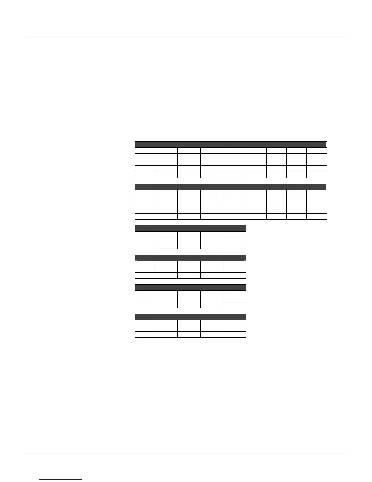
The table below displays the input and output parameters available for the CD600 Plus calibration.
AI – Auto
AI1 AI2 AI3 AI4 AI5 AI6 AI7 AI8
0V 0.000 0.000 0.000 0.000 0.000 0.000 0.000 0.000
1V 1.000 1.000 1.000 1.000 1.000 1.000 1.000 1.000
3V 3.000 3.000 3.000 3.000 3.000 3.000 3.000 3.000
5V 5.000 5.000 5.000 5.000 5.000 5.000 5.000 5.000
AI – Manual
AI1 AI2 AI3 AI4 AI5 AI6 AI7 AI8
0V 0.000 0.000 0.000 0.000 0.000 0.000 0.000 0.000
1V 1.000 1.000 1.000 1.000 1.000 1.000 1.000 1.000
3V 3.000 3.000 3.000 3.000 3.000 3.000 3.000 3.000
5V 5.000 5.000 5.000 5.000 5.000 5.000 5.000 5.000
CO 0-20mA
CO1 CO2 CO3 CO4
0% 0.000 0.0p00 0.000 0.000
100% 20.000 20.000 20.000 20.000
CO 4-20mA
CO1 CO2 CO3 CO4
0% 4.000 4.000 4.000 4.000
100% 20.000 20.000 20.000 20.000
VO 0-5V
VO1 VO2 VO3 VO4
0% 0.000 0.000 0.000 0.000
100% 5.000 5.000 5.000 5.000
VO 1-5V
VO1 VO2 VO3 VO4
0% 1.000 1.000 1.000 1.000
100% 5.000 5.000 5.000 5.000
Analog Input
The analog inputs are 0-5V voltage inputs. To convert the voltage inputs into 0-20mA current inputs,
connect the 250 Ω shunt resistor to the terminal.
To calibrate an analog input J (J = AI1 to AI8), follow these steps:
a) Check if the input to be calibrated will work as current or voltage input. If it will work as a current
input, it is recommended to use the same shunt resistor that will be used during operation;
b) Connect the voltage or current generator with indicator to the terminals corresponding to the J
input;
c) Select the output from the J analog input block to be displayed on the controller. Be sure that the
square root extraction and linearization function are not activated;
d) Connect the computer to the controller through the ICS2.0-1 interface;
e) Go to the Tool menu and click Calibration to open the Calibration dialog box. Select the device
address using the Identification Address value and click the button Look to locate the device: