Library of Function Blocks
4.51
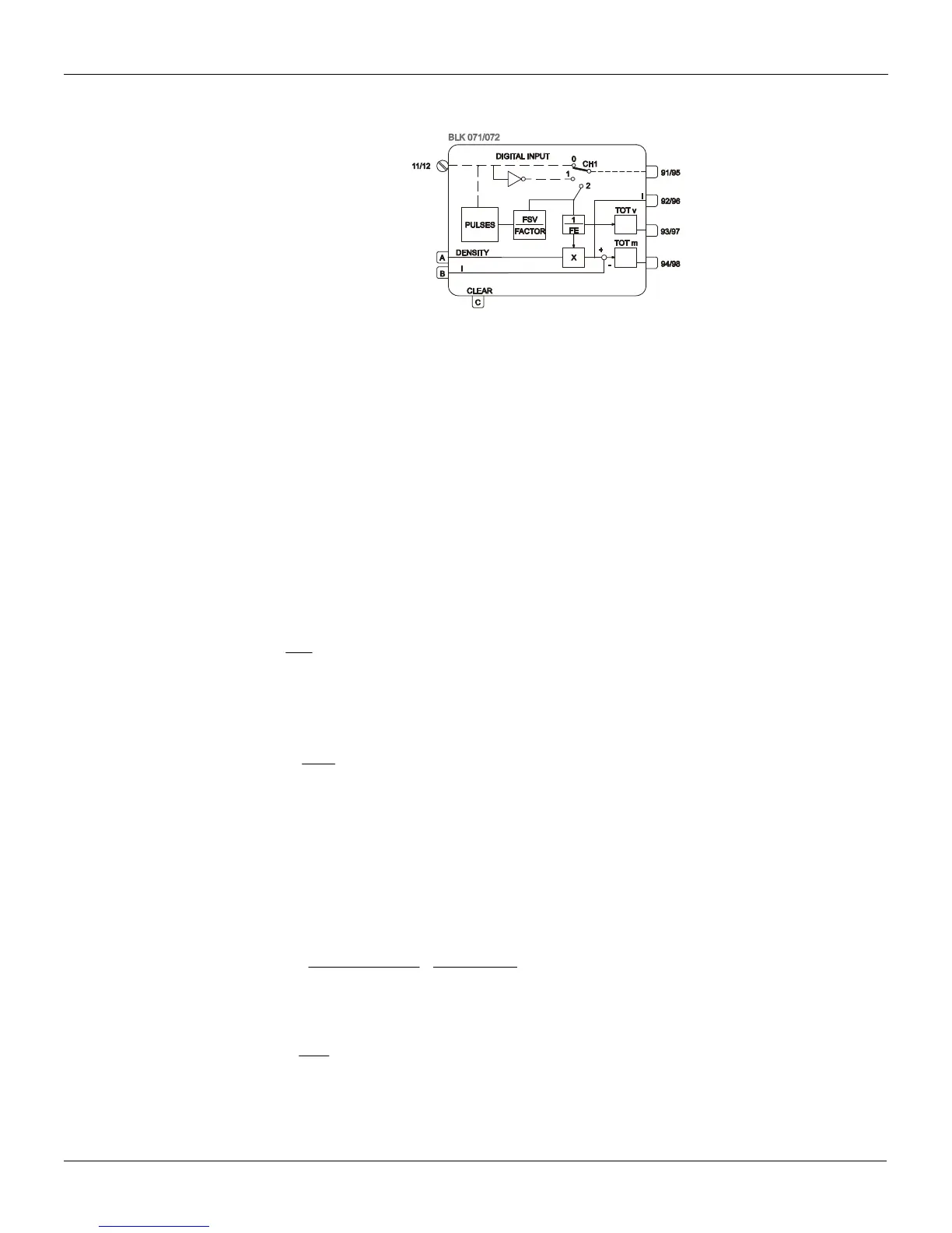
Function 19 - Pulse Totalization Input (P/DI)
Operation
This block can be used as a digital input or for the input of pulses coming from turbine flow meters,
or almost any type of pulsing signal for frequency measurement.
Working as a pulse input, it allows the frequency correction by the turbine factor and by the density.
The pulse subtractor input allows totalization of the deviation between two frequencies in one
bidirectional totalizer.
DEFINITION OF THE BLOCK FUNCTION (CTYP)
The block is normally used as digital input,
CTYP=0. If CTYP=1, it can be used to receive pulses,
and convert the frequency to an analog signal.
TURBINE FREQUENCY RANGE (CMFR)
In order to optimize the microprocessor time distribution, it is recommended to specify the turbine's
frequency range. There are two ranges: one below and another above 500 Hz.
If CMFR=0 the update time for the frequency to analog conversion is one input cycle.
Example: An instantaneous input of 400 Hz.
2.5ms =
400
1
= t
If CMFR=1 the update time for the frequency to analog conversion is eight input cycles.
Example: An instantaneous input of 1000 Hz.
ms8 =
1
.8 = t
1000
Note: As the frequency approaches 0 Hz the update time will be longer. However it is only for
very low frequencies that the update time is longer than the controller cycle.
TURBINE FACTOR (AFSV) AND ADJUSTMENT FACTOR (AFTR)
In turbine or vortex type meters, a factor for each type of fluid determines the number of pulses per
unit of volume.
This factor is provided directly by the meter manufacturer or is calculated as follows:
FTR is normally called the turbine K-factor.
(1)
] vol ofunits
]pulses [
=
] vol ofunits [
q
V
] Hz [ f
= FTR
[
The conversion of frequency into flow is done by dividing the input frequency by FTR:
)2 (
FTR
f
=
q
V
Some manufacturers, however, use the so-called turbine factor, which is the reciprocal of the
previous factor: