Section 18
CONF600 Plus Tutorial
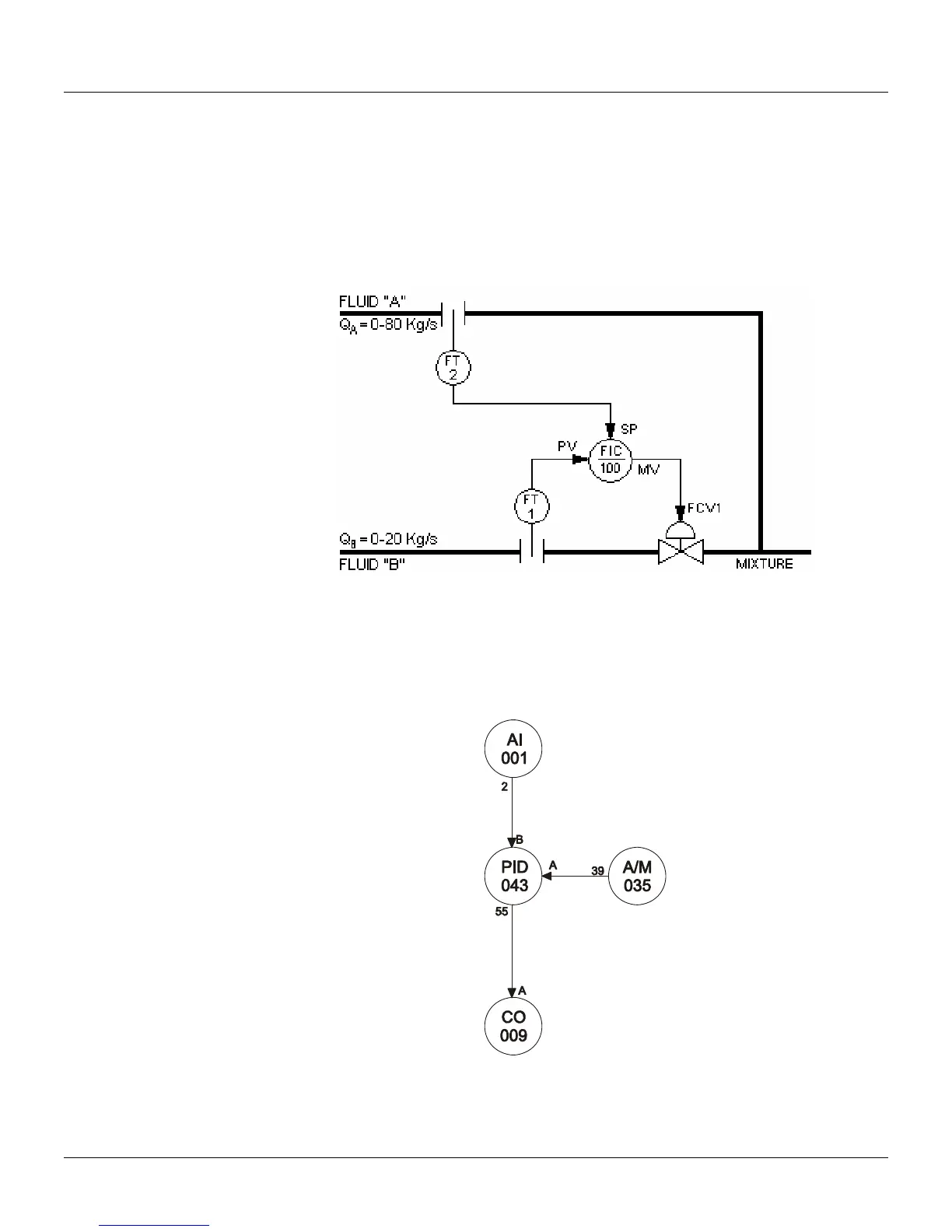
The figure below presents a simple example of a strategy control that will be implemented in the
CD600 Plus.
The focus will be on a project where Fluid A and Fluid B mix in a 4 to 1 proportion. Consider that the
transmitter at Fluid A measures 100% of flow at 80Kg/s while transmitter at Fluid B measures 100%
at 20Kg/s. A PID function block combined with other function blocks will be used to implement the
control logic.
Figure 18.1 - Desired Control Loop
The following figure shows what will be the final look of the strategy control implementation. Notice
that Function Blocks are represented with circles with an identification mnemonic (AI for Analog
Input, A/M for Auto-Manual Switch, etc.) and a unique number that represent its instance. Function
Block outputs are shown as numbers while inputs are represented by letters. A terminal may
represent a physical input or output.
Figure 18.2 - Strategy Control
18.1