Library of Function Blocks
4.55
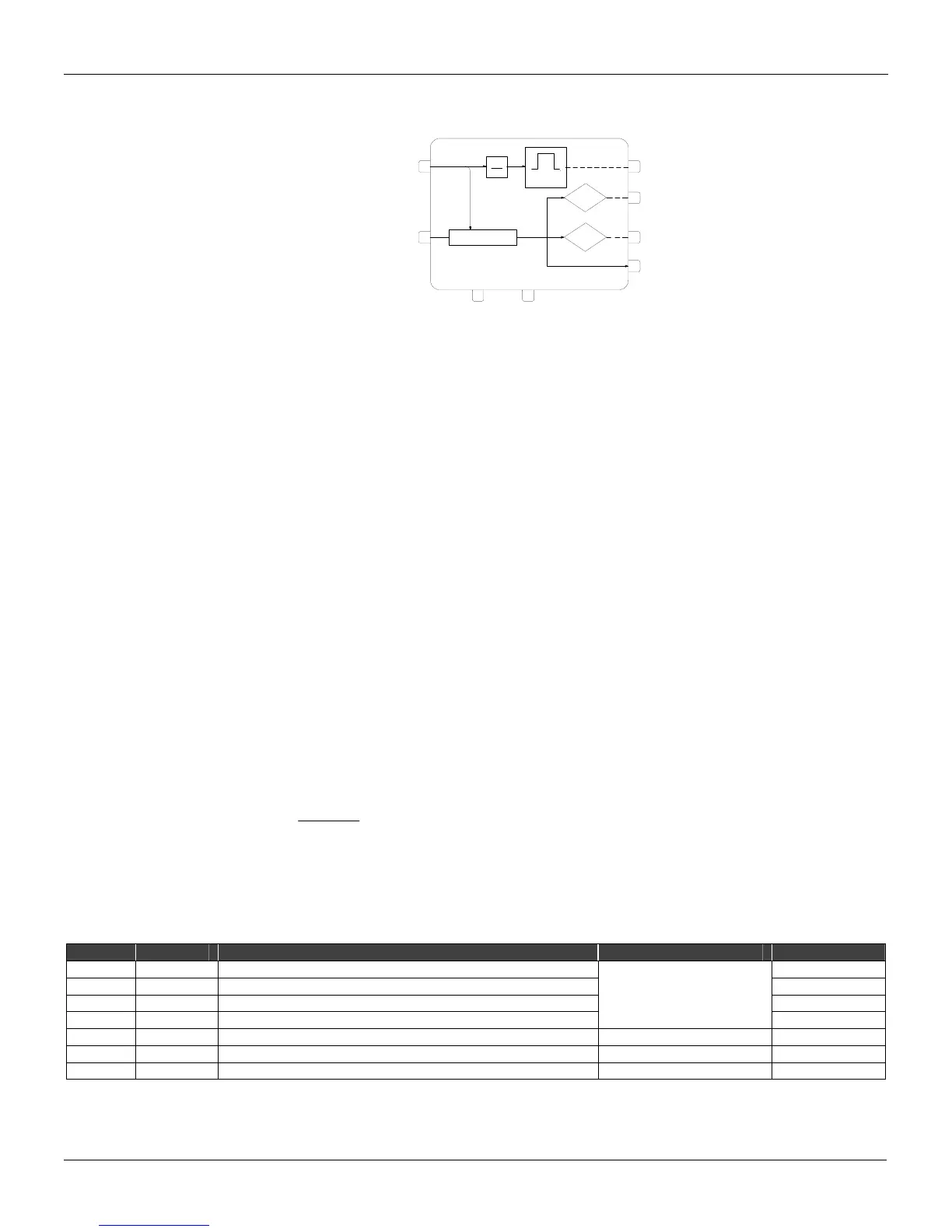
Function 20 - Batch Comparator (BAT)
Operation
The batch comparator block counts pulses and compares the count with two preset values, BAT1
and
BAT2. When the count reaches the value BAT1, the corresponding digital output of the block
goes to a high logic level and remains this way, until the counter is zeroed. The same is valid for
BAT2, which shall be programmed with a value greater than BAT1.
BLK 073
074
A
B
CD
99/103
100/104
101/105
102/106
BAT 1
BAT2
TOT
CLEAR
START
0 - 32000
1
G1
B1
B2
CYCLE
TIME
Δ
⏐
BAT1 and BAT2 are adjusted in parameters, ABT1 and ABT2, respectively.
This block also conditions output pulses for external counters, since pulses ΔI can only be used as
input for the internal blocks of the
CD600. The duration of the pulses for external counters is
determined by the Cycle Time Adjustment (see
Section 8 - Communication).
The parameter G1 determines the number of pulses at the input equivalent to one pulse at the
output. For example, if G1 = 10, there will be one pulse at the output for every 10 pulses at the input.
A high logic level at input C zeroes the counter and stops the count which will only start again if
there is a high logic level signal in
D. The return of D to a low logic level does not stop the count.
The counter may start from zero or from the value at input B. As input B accepts signals ranging
from 0.00 to 100.00, the start value of the counter is given by (B value x 100).
EXAMPLE:
The flow rate through a pipe line varies from 0 to a maximum of 72 Nm
3
/h. This pipe feeds a batch
reactor, that shall receive 10 Nm
3
of fluid. After totalizing 9.8 Nm
3
, the valve shall reduce the flow
rate to 10%. This is done to decrease the error caused by the system dead time.
For accounting purpose, the controller shall generate one pulse each 1 Nm
3
, to an external counter.
Configuration:
The analog totalization block (
Function 18) was programmed to provide one pulse ΔI each 0.01
Nm
3
. As the batch counter counts pulses, 10 Nm
3
correspond to 10/0.01 = 1000 pulses and 9.8/0.01
= 980 pulses. Each pulse for the external counter shall correspond to 1 Nm
3
.
Therefore, one pulse at the output (1Nm
3
) will correspond to G1 pulses at input (0.01Nm
3
).
100=
Nm
3
0.01
Nm
3
1
= G1
Therefore, the block shall be programmed as follows:
ANOP = 100
ABT1 = 980
ABT2 = 1000
TYPE MNEM DESCRIPTION RANGE DEFAULT
I LIA Input A - Increment 0
I LIB Input B - Counter start value 0
I LIC Input C - Clears counter 0
Addresses
0 to 170 / 225 to 240
I LID Input D - Starts Counting 0
I ANOP Number of input pulses corresponding to one output pulse 0 - +32000 0
I ABT1 Preset value in BAT 1 0 - +32000 0
I ABT2 Preset value in BAT 2 0 - +32000 0
Number of Bytes per Type of Parameter: A = 6 C = 0 L = 8