Section 9
9.1
INSTALLATION
Initial inspection
After receiving the CD600 Plus, check:
• If the model of the device corresponds to your purchase;
• If the device has not suffered external damage in the handling and/or transportation;
• The instructions manual and the CONF600 software CD is attached to the manual, as ordered.
LOCAL CONDITIONS FOR INSTALLATION
Power Supply
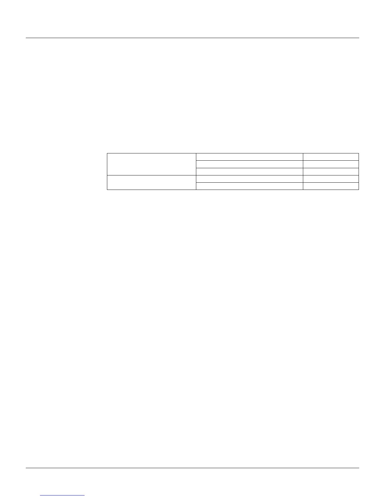
To obtain a stable and reliable system operation, it is required a high quality energy system,
following the requirements on the table below:
Voltage Variation 85-264 Vac
Frequency Variation 48 to 64Hz
AC Supply @ 85-264 V 47-65 Hz
Maximum Energy Interruption Period 14 ms (100 Vac)
Voltage variation 20-30 Vdc
24 Vdc
Power Suply
Maximum Energy Interruption Period 14ms (24Vdc)
Table 9.1 Power Supply Requirements
Environment Conditions
The temperature and relative humidity in the control room should be within the ranges specified
below:
• Temperature: 0 to 60° C
• Relative Humidity: 5 to 90% RH (non condensed).
• Storage temperature: -25 to 70° C
Air purity
The amount of dust in the air of the control room should preferably be controlled to below 0.2 mg/m
3
. It
is particularly desirable to minimize the corrosive gases and other conductive particles in the air.
Vibration
The equipment should be located where it is not subjected to vibration greater than:
Acceleration: g ≤ 0.3 g;
Frequency: f ≤ 100 Hz;
Amplitude: a = 500*g/f
2
(mm).
Precautions Against Electromagnetic Noise
The noise should be the least possible, in order to avoid interference with the equipment.
a) Transceiver
When using a transceiver in the control room, the following precautions should be observed:
• Never use a transceiver in the surroundings (less than one meter) of any instrument or within any
panel;
• The antenna of the transceiver should be set at least one meter away from the instrument or the
wiring of the instrument;
• The output of the transceiver should be limited to 1 W or less;
b) Noise From Relays
• To prevent noise and protect contacts, it is recommended the use of transient suppressors in each
relay or solenoid coil, See the item “Precautions using relays” – page 9.7.
c) Grounding Quality
The grounding quality is associated with noise suppression. The equipment, noise shield and the
housing should be grounded, as described in the item “Grounding” - page 9.4. The noise
suppression can also be improved if the signal cables are properly arranged. For better details,
please refer to the item "Signal Cable Installation" – page 9.7.