CD600 Plus - User's Manual
4.60
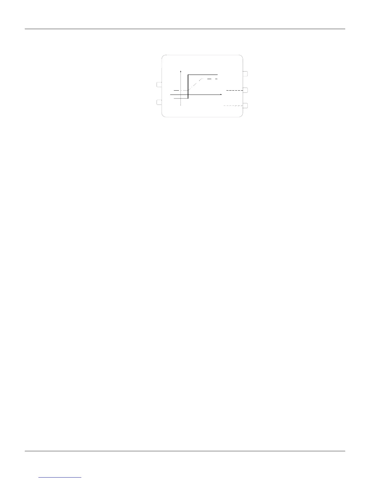
Function 23 - Limiter With Alarm (LIMT)
Operation
The function of this block is to limit a signal within static or dynamic limits. As the variable reaches
one of these limits, it can generate a high logic level signal. The block also generates an alarm
every time the variable
"Rate-of-Change" reaches a preset limit.
B
119/122
125/128
120/123
126/129
121/124
127/130
S
G.B+B
LL
E
G.B+B
HH
RATE OF CHANGE
ALARM
LIMITER
LARM
t
The inputs can vary from -102.00 to +102.00% and the output from 0 to 100%.
STATIC LIMITS
By connecting the variable
A to the input A and keeping the input B disconnected or with 0%, the signal
A will be limited between B
L
and B
H
, i. e., the output signal Y will be:
Y = B if A
≤
B
L L
Y = A if B < A < B
H
L
Y = B
H
if A
≥
B
H
B
L
and B
H
are adjusted at the parameters ABL and ABH, respectively.
DYNAMIC LIMITS
In this case, the limit is set by the variable
B, which is connected to the input B. In order to give more
flexibility, the limits can be established with individual gains and polarities.
Y = B . G
L
+ B if A
≤
B . G + B
L L L
Y = A if B . G + B < A < B . G + B
H
L L H
Y = B . G
H
+ B
H
if A
≥
B . G
H
+ B
H
LIMIT ALARM
Whenever the variable reaches the limit, the digital output "
Limiter Alarm" goes to a high logic level. At
the parameter
CLIM, it can be specified which limit actuates the digital output: the low limit, the high
limit or both.
The alarm can also be annunciated on the instrument Front Panel. To do that, the parameter CFRT=1,
3, 4, or 6 shall be programmed, according to the desired effect.
In order to avoid an output oscillation of the discrete output signal, as the variable is very near to the
limit value, the hysteresis can be used, which acts in the same way of the
Function 22 - Alarm. The
hysteresis is adjusted in the parameter
ADB.
RATE-OF-CHANGE LIMIT AND RATE-OF-CHANGE ALARM
The output
Rate-of-Change can be limited through the parameter ASLW.
The digital output "Rate-of-Change Alarm" switches to a high logic level whenever the
Rate-of-Change reaches the limit value introduced at the ASLW parameter. At the same time, the
alarm can be shown on the Front Panel when
CFRT is 2, 3, 5, or 6.
Note that when A changes faster than ASLW, the output changes at the "Rate-of-Change Limit"
value, and it keeps this rate until the output A reaches the new A value or one of the limits. Within this
period, the output "
Rate-of-Change Alarm" keeps the high logic level.
The Rate-of-Change Limit can be applied in modules, i.e, the limit applies for both increasing or
decreasing signals or it can be applied for a particular direction.
When the limit is for any direction, CLIM must be configured with 0, 1 or 2.