Quick Guide of Installation
A.3
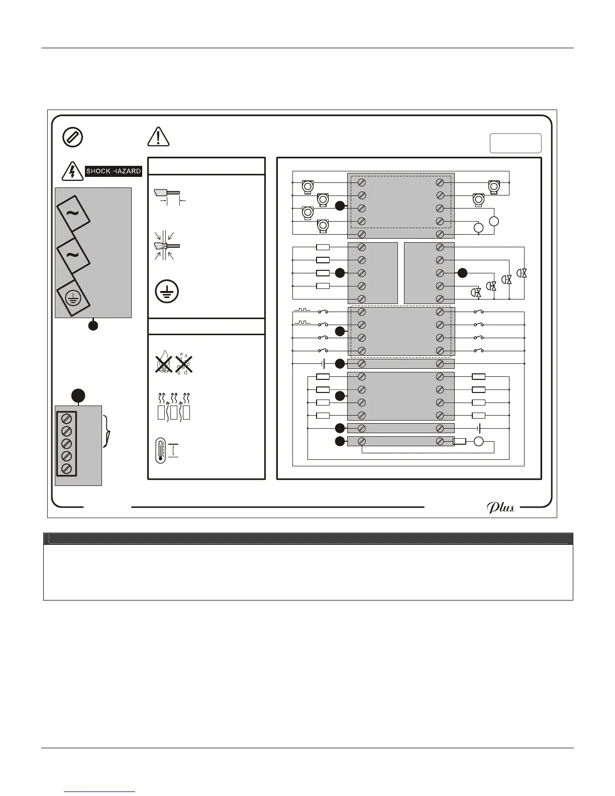
Electrical Installation of the controller
Figure 5 and 6 show the labels attached to the CD600 Plus side, AC and DC model, respectively.
See through theirs legend the terminals meanings.
Fus
85 -
Ma
50 -
265Vac
x 18VA
60Hz
e 1A
Model:
CD600 Plus - A
Serial Number:
EIA-485TRCV-
REF
GND
VCC
TRCV+
!
WARNING: Look at the Instruction Manual
before connect to the Power Supply!
Operational Temperature:
0ºC - 60ºC
32ºF 140ºF-
Instalation
Operation
Refer to the MANUAL for connections detail and firmware version.
Ø 0.08 - 2.5mm
2
Certify that only the
uncovered wire is
connected to the
Terminal Block!
Connect the GROUND
before use!
9
mm
Do NOT block the
airflow between
devices!
Keep away from
Fire and Water!
Use shunt resistor
for current input
Dry contact
or Voltage
9-VO4
10-GNDA
11-DI1
12-DI2
13-DI3
14-DI4
15-VEXT2
21-FAIL
1-AI1
3-AI3
4-AI4
6-VO1
7-VO2
8-VO3
2-AI2
5-24V
16-DO1
17-DO2
18-DO3
19-DO4
20-VEXT
DI5-32
DI6-31
DI7-30
DI8-29
DO5-27
DO6-26
DO7-25
DO8-24
GNDD-23
FAIL-22
GNDA-38
GNDA-33
GND2-28
CO1-37
CO2-36
CO3-35
CO4-34
AI5-42
AI6-41
AI7-40
AI8-39
1
8
7
6
4
32
1
5
9
10
smar
CD600
LEGEND
X – Analog Input.
Y – Voltage analog output.
Z – Current analog output.
[ – Digital input.
\ – External power supply for digital input.
] – Digital output.
^ – External power supply for digital output.
_ – Fail.
` – Power supply terminals.
a – EIA – 485 – Communication.
Figure 5 – Side label with the terminal block diagram for the CD600 Plus AC model.