CD600 Plus - User’s Manual
A.2
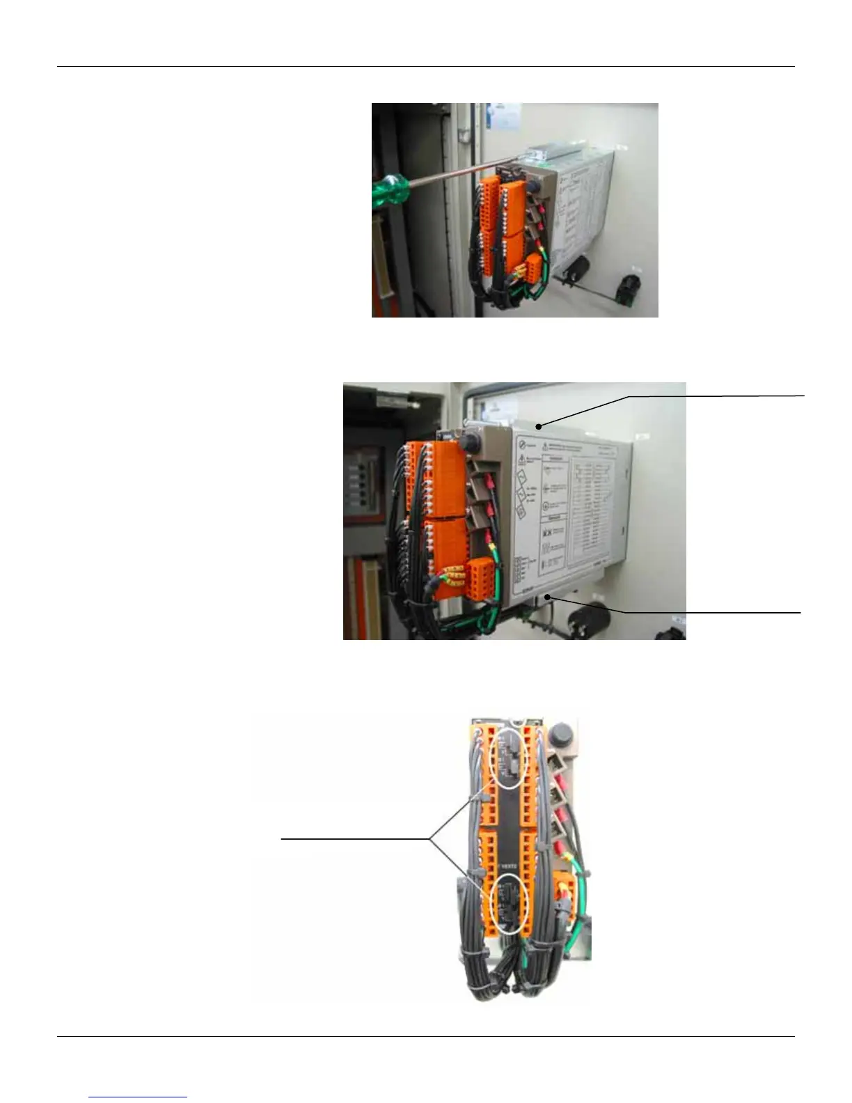
Figure 2 shows the screwdriver and the fixing clip bolt of the CD600 Plus (back view of the panel)
Figure 2 – Screwdriver on the CD600 Plus fixing clip bolt
The figure 3 shows the lower and upper fixing clip inserted in the opening of the CD600 housing to
attach it to the panel.
Upper fixing clip
Lower fixing clip
Figure 3 – CD600 Plus Fixing clip
Figure 4 shows the correct way to tie the cables on the CD600 Plus back part, so that access to the
shunt resistors is not obstructed.
Free access to shunt
resistors configuration.
Figure 4 – Correct way to tie the terminal block cables.