CD600 Plus - User's Manual
4.30
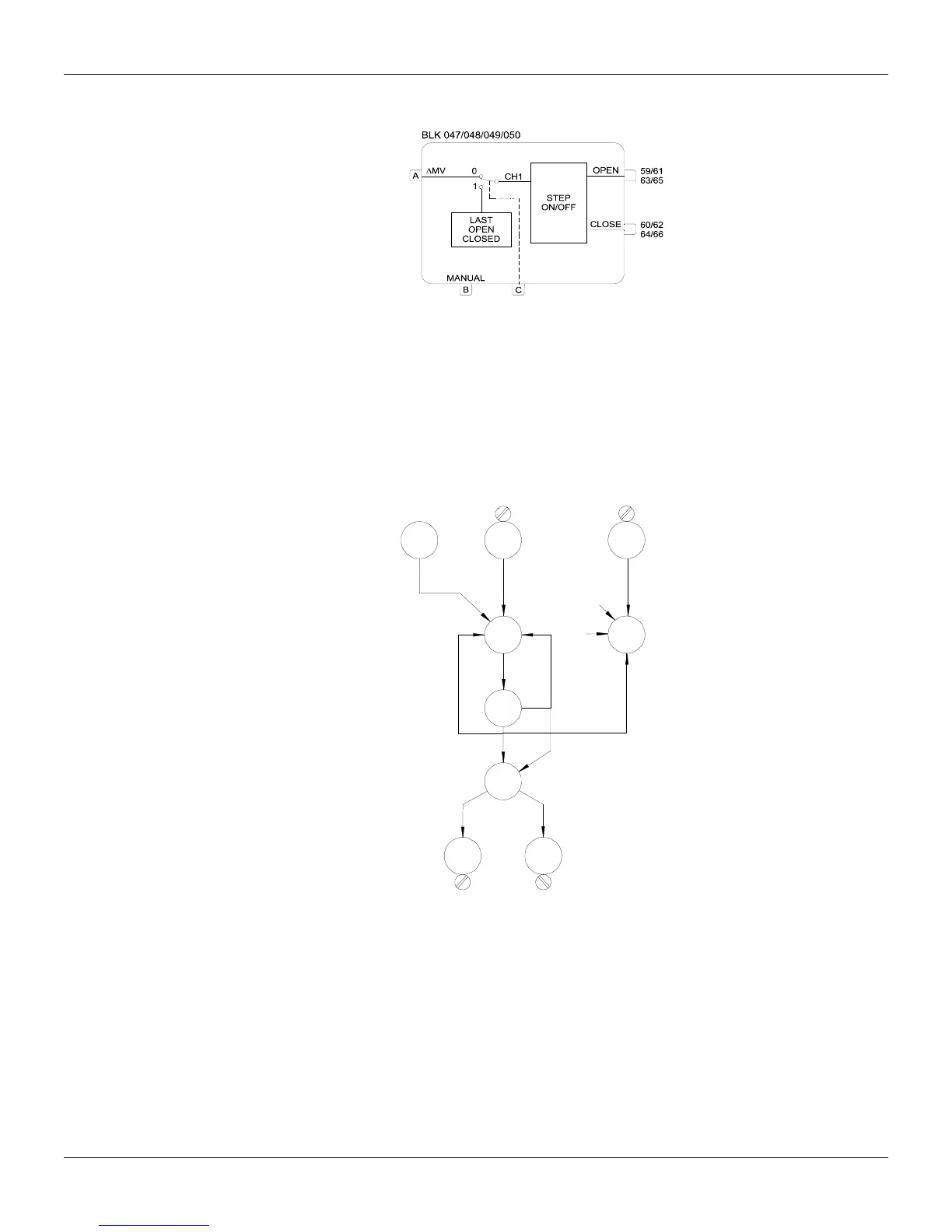
Function 11 - Step Controller (STEP)
Operation
This block is used in control loops with electrical final control element, such as rotating electric
actuators.
This block always operates in conjunction with a block of the Function 09 - Advanced PID and one
block from Function 08 - Automatic/Manual Switch. The PID and A/M blocks are connected as
usual. The analog output of the A/M Station (39,41,43 or 45) is connected to the input A of the Step
Control block and the status output (40, 42, 44 or 46) to the input B. The usual configuration is
shown on the Figure 4.11.1.
VALVE POSITION
(If avaliable)
L/R
031
PID
039
FV
027
MND=RET
BLK 043
BIA=50
AI
001
PV
2
225
2
C
A/M
035
40
39
47
225
B
B
59 60
6A 5A
DO
019
DO
020
STEP
047
B
D
D
4
AI
002
Fig 4.11.1 - Basic Configuration for a Step Control
It is recommended to use the advanced PID, because the gap control works as a dead band. This is
hen the variable is close to the Setpoint. required to avoid contact chattering, w
When the control is in the automatic mode, the block is sensitive to incremental variations at input A.
Output depends on this variation and on adjustments in parameter AVOT (Valve opening time) and
PL (pulse width). AW
AVOT must be adjusted with the approximate time required for the valve to go from fully closed to
fully open. The output characteristics also depend on AWPL - the minimum pulse width.
Proportional and Derivative actions of the PID are transformed into a pulse, whose duration depends
on the P and D gains, on the error and on the time required by the valve for a complete excursion
AVOT). (