CD600 Plus - User’s Manual
3.2
THE LOOPS
A Loop is a set of interconnected blocks with a certain purpose. It has a single man-machine
interface for the manipulation and visualization of data by the front panel of the controller. The
maximum number of loops per CD600 is 4.
The CD600's program also offers a configuration workspace named General Loop, "LOOP G"
which contains only blocks that may be simultaneously used by more than one loop. An example of
information maintained in the General Loop are the coordinates of the points used by a linearization
curve that may be used by several Analog Inputs simultaneously.
Tags
The Tag (Loop identification, see below) of the General Loop will always be the Tag of the whole
configuration. All configurations must have a General Loop, even if the program contains only one
control Loop. If no blocks are configured for the General Loop, at least a Tag must be given.
How to Program the CD600 Plus
When the CD600 Plus leaves the factory, with a default configuration named "4 LOOPS" (see
Section 5). This configuration can be changed to fit a particular application, or can be replaced by a
new one.
A program can be created, can be changed, or have its parameters modified through a PC. The PC
will need an appropriate interface, the CONF600 Plus. The CONF600 Plus is a powerful user
interface; it can be installed in a laptop or PDA and can be executed in the field as far as the
hardware allows. The configuration is drawn with control blocks and links, in part, as a control
diagram or a wiring diagram in a CAD system. In the Help windows, parameter information, options
and limits can be found.
The CONF600 Plus allows continuous access to all parameters and input/output monitoring
parameters of the blocks, becoming easier to troubleshoot configuration failures. The CONF600
Plus also supplies user documentation with configuration hardcopies, and disk storage. Please refer
to the CONF600 Plus section in this manual for further details.
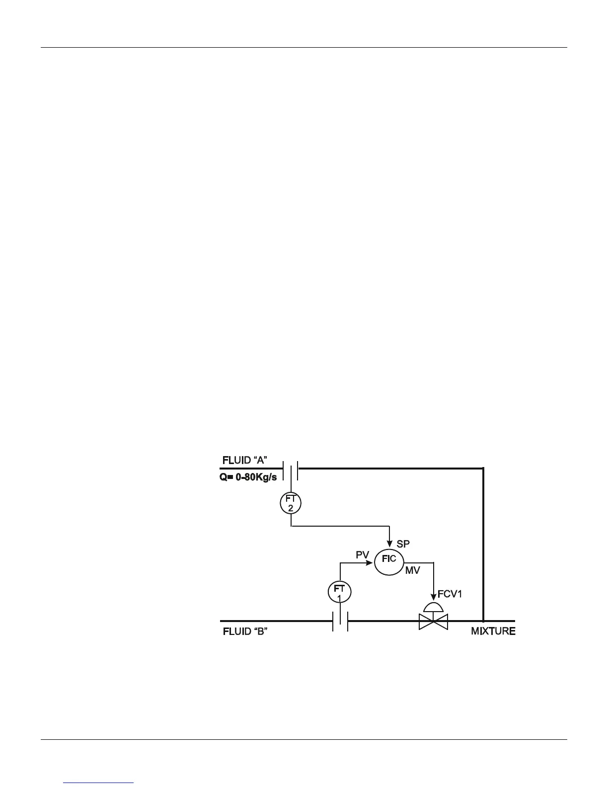
Example of a Configuration
The following control strategy can be implemented on the CD600 Plus:
Figure 3.1. Designed Control Loop
The Fluid B flow should be controlled to be the same as Fluid A. There is an example in section 4,
Function 12 - ARTH, where Fluids A and B are constantly controlled.
It is recommended to draw the configuration control using the block library as a reference. The
drawing should have block and terminal numbers, as indicate in the following figure: