Section 3
3.1
PROGRAMMING
Operation
The programming of the SMAR CD600 Digital Controller is based on the concept of freely
interconnectable Function Blocks. The interconnection is done in accordance to the control
strategy defined by the user.
All the function blocks already exist in a part of the memory not accessible by the user.
Programming the controller means to configure it by calling the necessary blocks into the user
memory, NVRAM, link them together, set their Characterization and Adjustment parameters to fit
a specific application.
Exchange of information between the used control algorithm and the process is done by means of
the input and output Function Blocks (both analog and digital). By these blocks the programmed
configuration is "physically" connected to the controller terminal block. Therefore, for example, the
Analog Input block No.1 can only be used for reading and processing the signal which is connected
to the terminal 001 (first analog input).
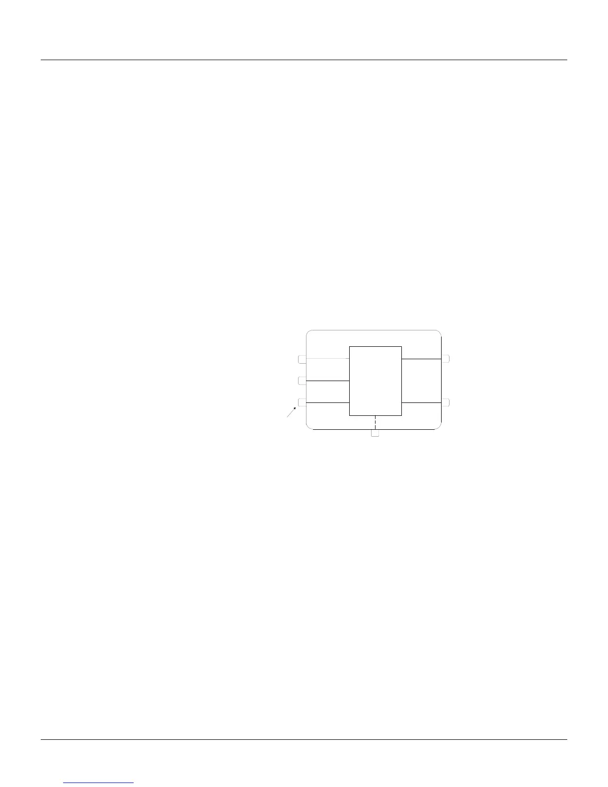
TYPICAL DESCRIPTION OF A BLOCK
The blocks described in Section 4 have a Control Function, consisting of one or more
mathematical and/ or logical operations. The function will relate block inputs with block outputs. The
inputs are designated by letters (A, B, C...), and outputs are designated by numbers. Exceptions are
the Analog and Digital input and output blocks, whose inputs, respectively outputs, are related to
hardwired terminals.
D
NALOG
INPUTS
A
B
C
HIGH
LOW
SELECTOR
LOW
DISCRETE INPUTS
140/142
144/146
139/141
143/145
HIGH
Fig 3A - Typical Block
The numbers related to the block outputs are addresses. Each number refers exclusively to a
certain output of a certain block and vice versa.
Each block has one Linking Parameter (L) for each input. A block with 3 inputs has the Linking
Parameters LIA, LIB, and LIC (Link Input A, B and C). If the HIGH-LOW selector block shown in
Figure 3A has LIA=2, that means that the input A of that block is on.
As a block can perform several operations, the activations of these operations are defined by the
Characterization Parameters. For example, the Analog Input block offers a choice of
implementing SQuare Root extraction (CSQR=1) or not (CSQR=0). It offers also a choice to use
LINearization (CLIN=1) or not (CLIN=0) - (See Figure 3B).
Constants in the Function Blocks that require frequent changes during process operation are called
Adjustment Parameters (ADJ Parameters). The same Analog Input block has an adjustable filter,
which has a time constant adjustable by ATIM.
There are two types of signals between blocks: scalar and discrete. Scalar are continuous signals
while discrete are on-off type of signals.
The signal transfer through block link is always made in the form of percentage, even if the signal is
discrete (0% for low logical level 0 and 100% for high logic level 1). A scalar signal, connected to an
input prepared to receive discrete signals, will be interpreted as follows:
- less than 70%: level 0
- more than 80%: level 1
- between 70% and 80%: previous state
The output signal of a block can be received by as many inputs of blocks as desired.