Quick Guide of Installation
A.5
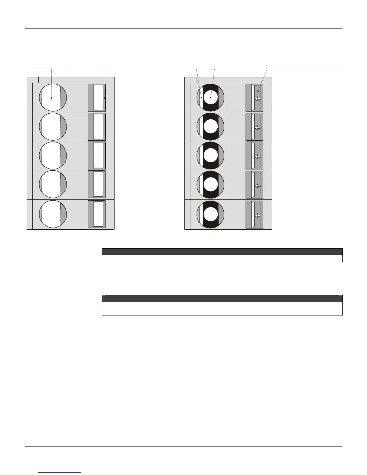
See figure 7
CLOSED CONNECTOR
OPENED
CONNECTOR
INSERT THE
SCREWDRIVER
IN THIS EMPTY
SPACE
ROTATE THE SCREWDRIVER
TO PRESS THE LEVER AND
OPEN THE CONNECTOR BESIDE.
INSERTED WIRE
Figure 7 – CD600 Plus terminal block with its closed and open terminals.
ATTENTION
Connect the housing ground before supplying the equipment..
Control strategy configuration
Consult the CONF600 in the user manual for installing the configuration software.
NOTE
CD600 Plus is factory-configured to work with 4 loops. See in the CD600 Plus manual for more
information about this subject.
Establishing the communication between the controller and the
computer
1 – Using the computer serial gate
Connect the ICS 2.0P interface in the identified terminal in the label of the CD600 Plus with the
specific cable. (See the ICS 2.0P manual for more details). Figure 8 shows the connections of the
cable with the equipments.