CD600 Plus - User’s Manual
A.4
20 -
Ma
30Vdc
x 24W
Fuse 1.25A
Model:
CD600 Plus - D
Serial Number:
EIA-485
smar
CD600
TRCV-
REF
GND
VCC
TRCV+
!
WARNING: Look at the Instruction Manual
before connect to the Power Supply!
Operational Temperature:
0º C 60º C
32º F 140º F
-
-
Instalation
Operation
Refer to the MANUAL for connections detail and firmware version.
Ø 0.08 - 2.5mm
2
Certify that only the
uncovered wire is
connected to the
Terminal Block!
Connect the GROUND
before use!
9
mm
Do NOT block the
airflow between
devices!
Keep away from
Fire and Water!
DI5-32
DI6-31
DI7-30
DI8-29
DO5-27
DO6-26
DO7-25
DO8-24
GNDD-23
FAIL-22
GNDA-38
GNDA-33
GND2-28
CO1-37
CO2-36
CO3-35
CO4-34
AI5-42
AI6-41
AI7-40
AI8-39
Use shunt resistor
for current input
Dry contact
or Voltage
9-VO4
10-GNDA
11-DI1
12-DI2
13-DI3
14-DI4
15-VEXT2
21-FAIL
1-AI1
3-AI3
4-AI4
6-VO1
7-VO2
8-VO3
2-AI2
5-24V
16-DO1
17-DO2
18-DO3
19-DO4
20-VEXT
32
1
9
4
5
6
7
8
10
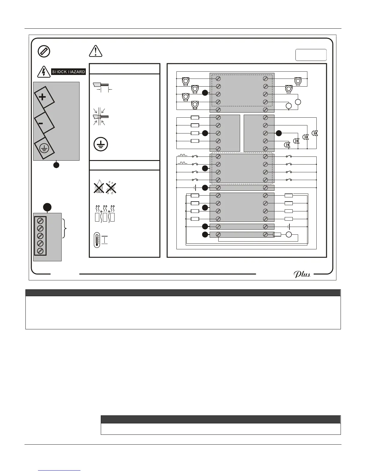
LEGEND
X – Analog Input.
Y – Voltage analog output.
Z – Current analog output.
[ – Digital input.
\ – External power supply for digital input.
] – Digital output.
^ – External power supply for digital output..
_ – Fail.
` – Power supply terminals.
a – EIA – 485 – Communication.
Figure 6 – Side label with the terminal block diagram for the CD600 Plus DC model.
To insert the connection wire for Input/Output and terminal block communication, follow the steps
below:
1 – Insert the screwdriver in the rectangular cavity of the terminal blocks. (Do not force the
screwdriver in the block side, because it can damage it).
2 – Rotate the screwdriver at a 90º angle. The cavity for the wire insertion will open.
3 – Insert the uncovered part of the wire in the cavity and rotate the screwdriver again in the
opposite direction to press the wire in the cavity.
NOTE
To guarantee the electrical contact insert only the uncovered wire in the cavity.