CD600 Plus - User’s Manual
8.2
Digital Outputs (DO1 to DO8)
Quantity: 08
Type: Open collector (max. Vext = 30 Vdc; maximum current = 400 mA)
Internal Protection: reverse diode
Output Protection: Independent from the overcurrent protection for each output independent;
thermal protection for each output.
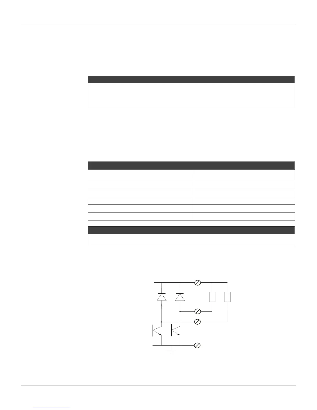
WARNING
Always use the "V Ext" when connecting inductive loads to the digital outputs. Refer to the connection
diagrams (Figure 8.3) and for V
EXT
(Figure 8.1).
It is recommended to use "V Ext", the same way, that when an external supply is available, to prevent damage
due to the overvoltage during the load switching.
NOTE: The V
EXT
protects the transistors through parallel built in diodes conncted to the “load”. See
Fig. 8.1.
NOTE: Inverting the digital outputs’ polarity will damage the equipment.
Digital Output to indicate the Controller Failed
If there is a failure in the main electronic board, the relay corresponding to this input will be in the
closed status.
ESPECIFICATION
Output Type
Solid-state relay, normally closed (NC),
isolated
Maximum voltage 30 Vdc
current 200 mA
Overload protection
Should be provided externally
Normal operation ct Open
Safe condition
NOTE
To meet the EMC standards requirements, the wires’ length to the failure relay must be less than 30 meters.
The power supply of activated load by the failure relay must not be from external network.
Remark: To protect the controller from reverse voltage damage, externally connect a snubber RC
circuit in parallel with the inductive AC load, or a diode for DC load.
VEXT
DO 1
DO n
N=2~8
GND
D
Figure 8.1. V Ext