Library of Function Blocks
4.13
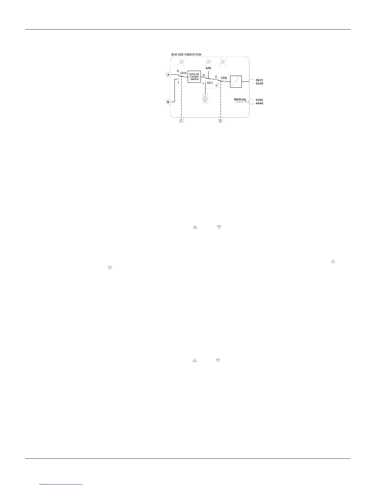
Function 08 - Automatic/Manual Station (A/M)
Operation
This block allows the operator to actuate the controller output directly, whenever necessary.
In the most common application, the output signal of one of the PID blocks is linked to the input A of
the A/M block, its output being linked to a current output block.
If the other inputs of this block are not used, switches CH3 and CH2 are permanently in position "0".
Switch CH1 may then be actuated by pressing the key <A/M> on the front panel, thus altering the
operation mode:
a) AUTOMATIC (CH1 in position "0"): letter M is unlit in the corresponding loop. Input A signal goes
to the block output after passing by a rate-of-change limiter (parameter ASLW) and by an
output signal limiter (parameters ALOW and AUPP).
b) MANUAL (CH1 in position "1"): letter M is lit in the corresponding loop. Output signal may then
be adjusted by the keys <
> and < >, its speed being determined by parameter ASPD,
with the limits set by parameters ALOW and AUPP.
Manual to Automatic transfer may be bumpless or hard. Both modes are described in the PID block
functions.
Automatic to Manual transfer is always balanceless. The register, actuated by the keys < > and
< >, always tracks the value available at the output of the Rate-of-Change limiter while in
automatic operation.
After a power failure or a manual reset of the controller, switch CH1 returns to operation according to
parameter CHST; it may return in Manual, Automatic or in the last position prior to the power failure
or to the reset.
It is also possible to block the <A/M> key, locking the controller in Automatic or Manual, by means of
the parameter CCH1.
FORCED MANUAL
Forced Manual mode is implemented by actuating switch CH2 by means of input D:
a) A low logic level in D keeps CH2 in position "0" (NORMAL OPERATION).
b) A high logic level in D switches CH2 to position "1" (FORCED MANUAL). In this situation, the
register actuated by the keys < > and < > takes the input value at position "0", just before the
switching.
Other features may be added to this mode. For further information, see description of parameters
CCH1, CST1, CLAM and CLMV.
SAFETY OUTPUT
The controller output may be driven to a safe value by switching CH3 to position "1", by means of
input C of the block. The output signal will then be the input B signal. This may be a constant or a
variable value, depending on which block it is originated.
If CH1 is in position "1" (equivalent to Manual), the letter M of the corresponding loop will be
continuously lit and the output signal will be the signal of input B in the instant prior to CH3
switching.