Installation
9.3
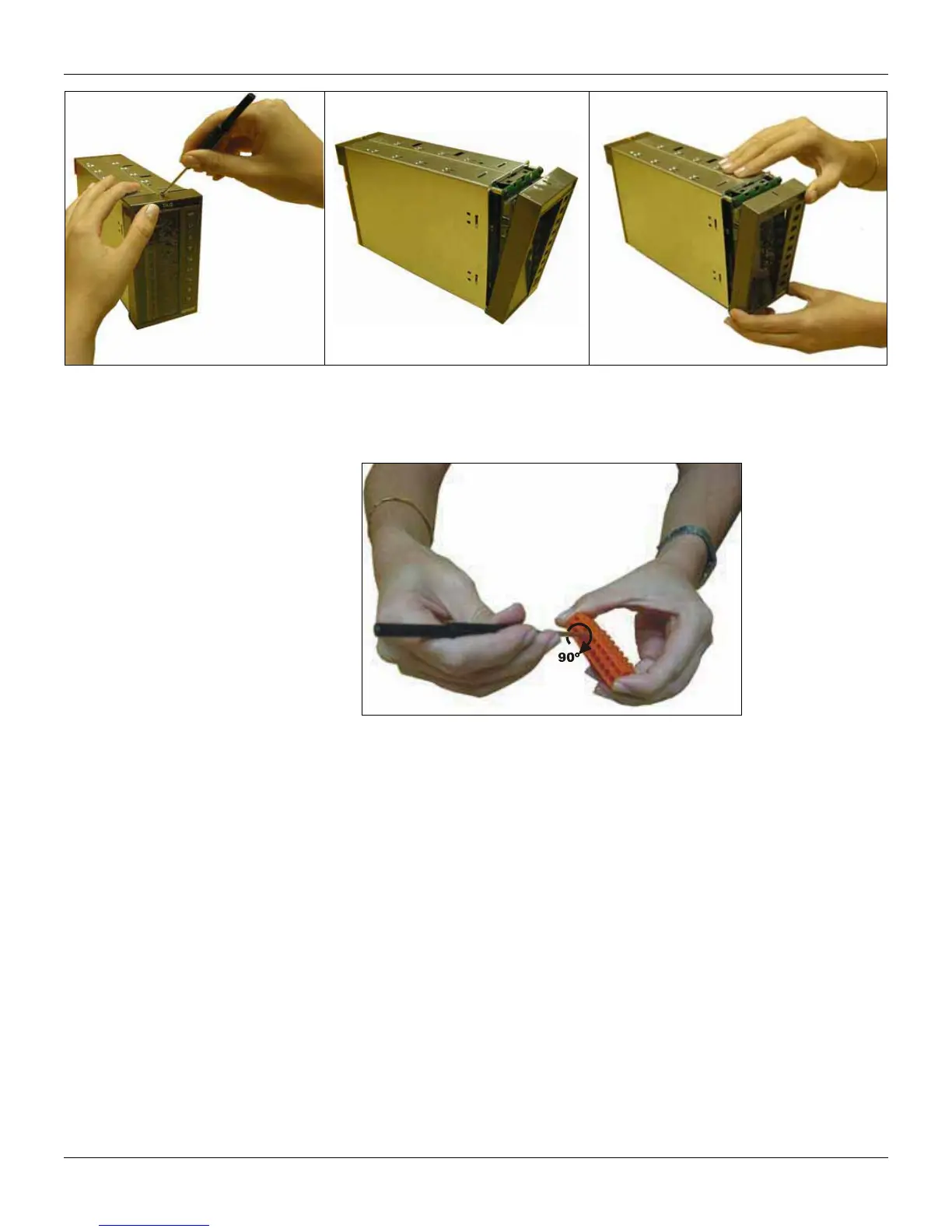
Terminal Block Assembly
To connect the wire on the terminal block, insert a screwdriver in one of the rectangular cavities of the
block. Give a 90 degree twist on the screwdriver, and the cavity will be open for the wire insertion. See
the figure below.
WIRING
Grounding
The purpose of grounding is not only to protect the operators from electrical shock, but to keep all
equipments on the same stable electrical potential. The grounding system should be of low
impedance, capable of absorbing currents from noises that cause malfunctioning of the system.
On the panel that the controllers will be installed, there should be two grounding buses:
• Housing Grounding bus: it corresponds to the plant grounding bus. That is where the housing of
each CD600 Plus (see Fig. 8.4 - pag. 8.5) should be connected (see Fig. 9.2).
• Analog Grounding Bus: It corresponds to the bus where the analog input and output return (-)
and the internal 24 Vdc power supply are connected. The analog grounding of each CD600 Plus
(see Fig. 8.4 - pg. 8.5) should also be connected to the bus (see Fig. 9.3).
Each controller should have its own connection for both kinds of grounding. See figures 9.2 and 9.3.