CD600 Plus - User’s Manual
9.2
EQUIPMENT INSTALLATION
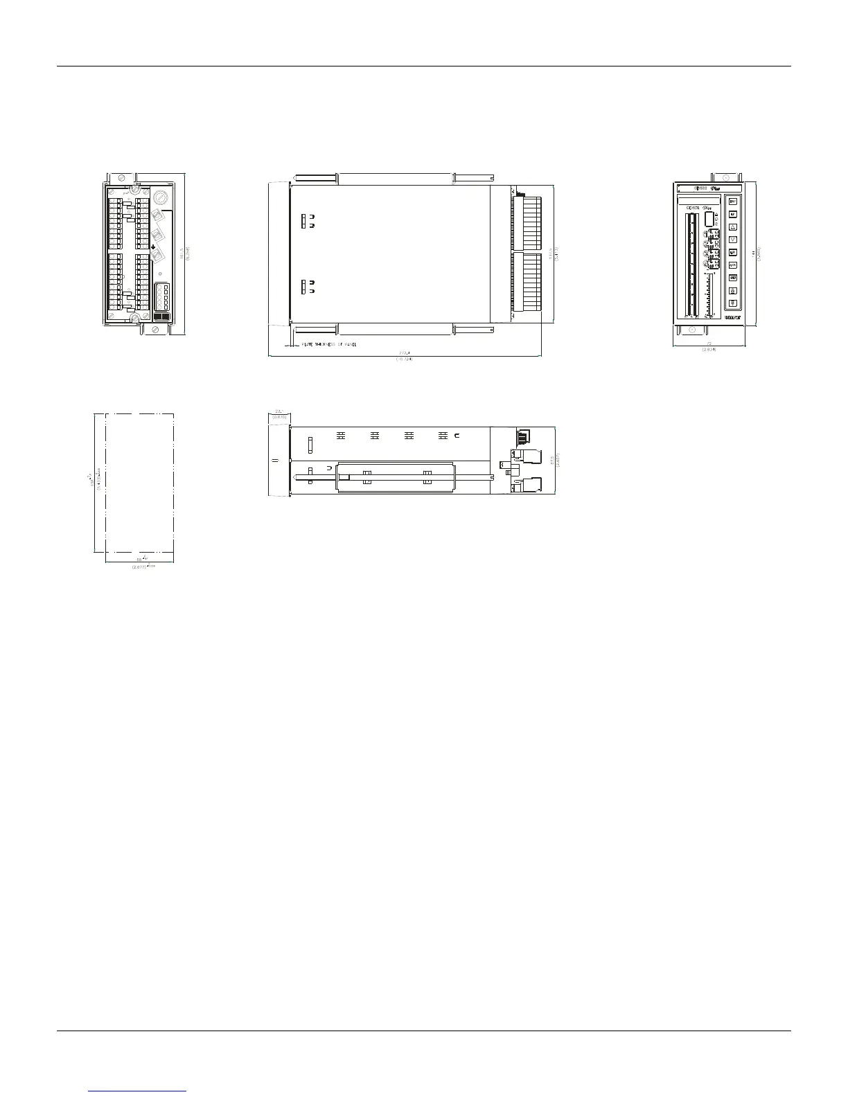
Dimensions
The dimensions of the controller and the cut in the panel, for the installation of the CD600 Plus, are
showed in fig. 9.1.
CD600
smar
VERTEX2
REAR
AC
F1
~
~
VIEW
FRONT PANEL
H
LE IN THE PANEL
Fig. 9.1 – Dimensional Drawing
Panel Layout
The factors that will determine the equipment distribution in the panel, are maintenance and
operation frequency. The following points should be considered:
• Group distribution of systems and sub-systems, following a relative order, or operational sequency
of the equipment;
• Placing in adequate height levels, following the principles of operationability;
• Operational priority, frequency of use, dimension and quantity of instruments;
• Priorities, risks and tasks of the operator.
Disassembling the Front Panel
Step 1: To disassemble the front, push the panel and insert a screwdriver in the hole, located at the
top of the front, as shown in the figure.
Step 2: Pull out the front panel, and remove the front.
Step 3: To re-assemble the front panel, attach the bottom and push the top until it is fastened.