Technical Specifications
8.5
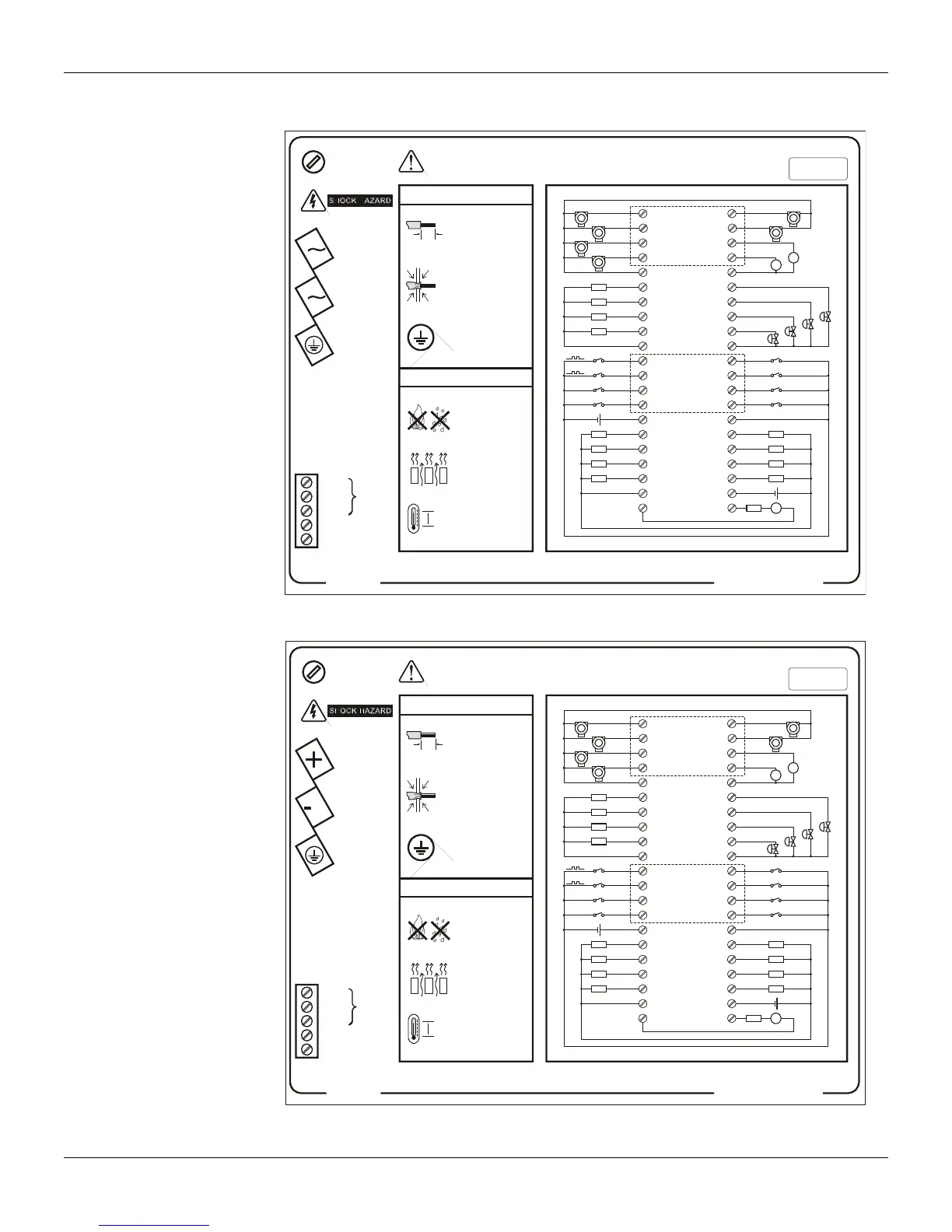
Rear Panel Diagram
85 - 265Vac
Max 18VA
50 - 60Hz
smar
CD600
Plus
Fuse 1A
Model:
CD600 Plus - A
Serial Number:
EIA-485
TRCV-
REF
GND
VCC
TRCV+
!
WARNING: Look at the Instruction Manual
before connect to the Power Supply!
Operational Temperature:
0º C 60º C
32º F 140º F
-
-
Instalation
Operation
Refer to the MANUAL for connections detail and firmware version.
Ø 0.08 - 2.5mm
2
Certify that only the
uncovered wire is
connected to the
Terminal Block!
Connect the GROUND
before use!
9
mm
Do NOT block the
airflow between
devices!
Keep away from
Fire and Water!
Use shunt resistor
for current input
Dry contact
or Voltage
9-VO4
10-GNDA
11-DI1
12-DI2
13-DI3
14-DI4
15-VEXT2
21-FAIL
1-AI1
3-AI3
4-AI4
6-VO1
7-VO2
8-VO3
2-AI2
5-24V
16-DO1
17-DO2
18-DO3
19-DO4
20-VEXT
DI5-32
DI6-31
DI7-30
DI8-29
DO5-27
DO6-26
DO7-25
DO8-24
GNDD-23
FAIL-22
GNDA-38
GNDA-33
GND2-28
CO1-37
CO2-36
CO3-35
CO4-34
AI5-42
AI6-41
AI7-40
AI8-39
Figure 8.4. CD600 Plus side tag with terminal diagram AC
20 - 30Vdc
Max 24W
smar
CD600
Plus
Fuse 1.25A
Model:
CD600 Plus - D
Serial Number:
EIA-485
TRCV-
REF
GND
VCC
TRCV+
!
WARNING: Look at the Instruction Manual
before connect to the Power Supply!
Operational Temperature:
0º C 60º C
32º F 140º F
-
-
Instalation
Operation
Refer to the MANUAL for connections detail and firmware version.
Ø 0.08 - 2.5mm
2
Certify that only the
uncovered wire is
connected to the
Terminal Block!
Connect the GROUND
before use!
9
mm
Do NOT block the
airflow between
devices!
Keep away from
Fire and Water!
DI5-32
DI6-31
DI7-30
DI8-29
DO5-27
DO6-26
DO7-25
DO8-24
GNDD-23
FAIL-22
GNDA-38
GNDA-33
GND2-28
CO1-37
CO2-36
CO3-35
CO4-34
AI5-42
AI6-41
AI7-40
AI8-39
Use shunt resistor
for current input
Dry contact
or Voltage
9-VO4
10-GNDA
11-DI1
12-DI2
13-DI3
14-DI4
15-VEXT2
21-FAIL
1-AI1
3-AI3
4-AI4
6-VO1
7-VO2
8-VO3
2-AI2
5-24V
16-DO1
17-DO2
18-DO3
19-DO4
20-VEXT
Figure 8.5. CD600 Plus side tag with terminal diagram DC