Library of Function Blocks
4.61
If the limit is for a particular direction, CLIM must be configured with 3, 4 or 5 and ASLW must be
adjusted with the respective signal:
+ for increasing signal
− for decreasing signal
OTHER APPLICATIONS
This block can also be used to compute the equation:
Output = G
L
. B + B
L
To do that, it is just enough to make A = 0% or to keep the input A free. The block is also used to
generate alarms. The dynamic limits are extremely useful in one of its most important applications:
combustion control with double cross limits.
This type of control tries to keep the air-fuel ratio strictly within the limits. A sudden change on the load
would require a corresponding air and fuel variation. The "double cross limits" prevents that the fastest
variable unbalance the desired ratio.
On conventional controllers it is done using relays to select high and low values plus the
adder/subtractor stations. Typically, this control is implemented as shown in the Figure 4.23.1.
Fig 4.23.1 - Combustion Control with double cross limits
This configuration allows the air flow (Q
a
) to vary just between (Q
c
- B
2
) and (Q
c
- B
1
) and the fuel
flow (Q
c
) to vary just between (Q
a
- B
4
) and (Q
a
- B
3
).
In this manner, even when there are large transients on the Master signal, the air and fuel flow
keeps the required ratio.
The limiter block perform the functions indicated inside the broken line area, i.e., two of these blocks
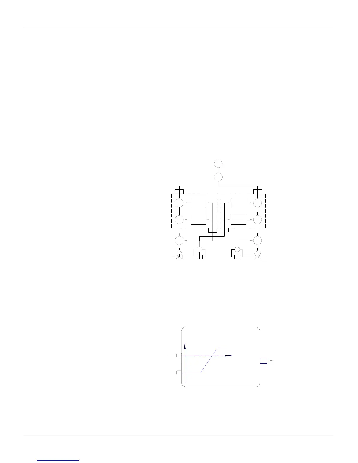
can implement the double cross limits function. The Figure 4.23.2 shows one of these blocks.
Fig 4.23.2 - Fuel Setpoint from a double cross limit configuration (TIC)
The Table 4.23.1 shows the block response to a Master signal variation and the air flow for G
H
= G
L
= 1, B
L
= -10%, and B
H
= 5%. The table rows show the instants in which the air flow or the fuel flow
have changed 5%.
TE
TIC
B G +B
HH
B G +B
LL
B G +B
LL
*
*
B
PV PV
FIC
SP
SP
>
>>
>
FIC
100
FUEL
AIR
B
*
A
A
*
B G +B
HH
SIGNAL FROM
MASTER TIC
0
B. G + B
LL
B. G + B
HH
119
FUEL
SET POINT
B
SIGNAL FROM
IR FLOW RATE