CD600 Plus - User's Manual
4.62
The air flow valve is slower than the fuel flow valve.
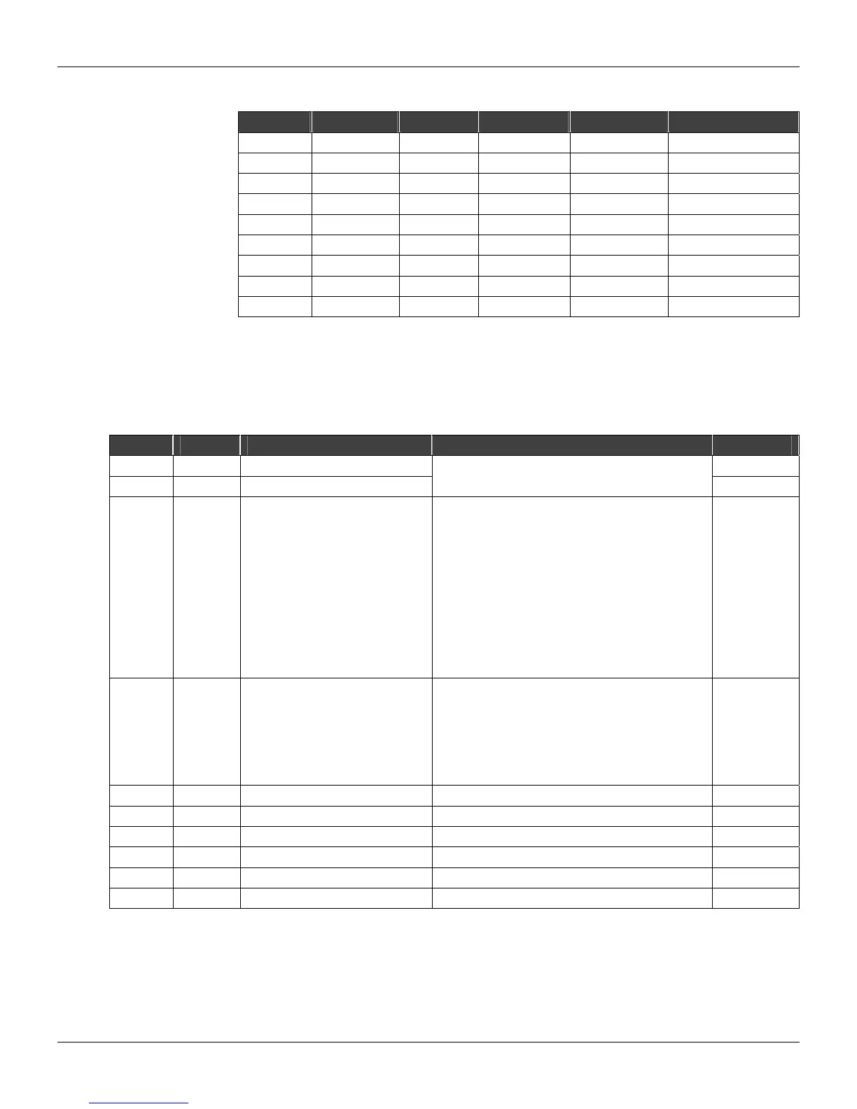
INST TS AN TIC OUTPUT AIR FLOW LOW LIMIT HIGH LIMIT FUEL SETPOINT
1 50 50 40 55 50
2 60 50 40 55 55
3 60 55 45 60 60
4 60 60 50 65 60
5 60 60 50 65 60
6 45 60 50 5 50
7 45 55 45 60 45
8 45 50 40 55 45
9 45 45 35 50 45
Table 4.23.1 - Block response to master signal variations
ly, as the air Setpoint is function of the fuel flow, according to a similar
but with
⎢B
L
⎢< ⎢B
H
⎪.
Note that the output for the fuel Setpoint is always between the low and high limits. It is supposed
that the fuel flow follows the Setpoint change within a very narrow time interval. The air flow follows
the fuel flow but more slow
table,
TYPE MNEM DESCRIPTION RANGE DEF LT AU
I LIA Input A (Variable) 0
I LIB Input B (dynamic limit) 0
Addresses
0 to 170/225 to 240
I CLIM
and Rate-of-Change Alarm
ate-of-Change alarm in modules and:
- Limiter alarm LOW and HIGH
dering (+)increase/ (
−)
ecrease signal and:
alarm LOW and HIGH
0
Limiter Alarm Output Actuation
R
0 - Limiter alarm LOW
1 - Limiter alarm HIGH
2
Rate-of-Change consi
d
3 - Limiter alarm LOW
4 - Limiter alarm HIGH
5 - Limiter
I CFRT Alarm(s) on the Frontal
e-of-Change Auto Ack.
0
0 – None
1 – Limit
2 - Rate-of-Change
3 - Limit/Rate-of-Change
4 - Limit Alarm Auto Ack.
5 - Rate-of-Change Alarm Auto Ack.
6 - Limit Alarm/Rat
C A-GL Low Limit Gain 0.000 - 30.000 0.000
P A-BL Low Limit Bias -300.00% to +300.00% 0.00
C A-GH High Limit Gain 0.000 to 30.000 0.000
P A-BH High Limit Bias -300.00% to +300.00% 1 00.00%
P A-DB Comparison Alarm Hysteresis 0.00% - 100.00% 0.00%
P ASLW Maximum Rate-of-Change -200.00 to +200.00% 200.00%/s
umber of Bytes per Type of Parameter: A = 12 C = 4 L = 4
N