CD600 Plus - User's Manual
4.50
The other output of this block provides the value to the internal counter. The counter has 8 digits.
These 8 digits are available only for input G of the visualization blocks. The four digits less
significant are available for the regular analog input (0,00% to 99.99%) of any block.The counting is
divided by 100. For example, the counting 09827125 shown in input G of the visualization block
would read 71.25% at the input of the other blocks.
The counter actualization capacity is limited to 120 countings per cycle. For a cycle of 0.2 s, the
maximum actualization capacity would be of 600 countings per second. The counting per cycle
which exceeds this value is stored, to be unloaded later. The number of countings per cycle should
be kept below the limit, in order to prevent a batch from being interrupted after the real value has
been passed. In order to avoid this problem, always keep:
120 < ) time (cycle x
ATU
AMFL
For cycle time adjustment, refer to
Section 8.
This block may also be used to generate pulses in a frequency adjustable by input
A. Maximum
frequency occurs when
A=100% and it depends on AMFL and ATU values.
Pulses thus generated may be used as Setpoint for a flow controller, where PV is measured with a
Turbine flow element. See example in
Function 19. The
counting is zeroed when there is a high level signal at input
B. The counting starts when input B is
back to the low logic level.
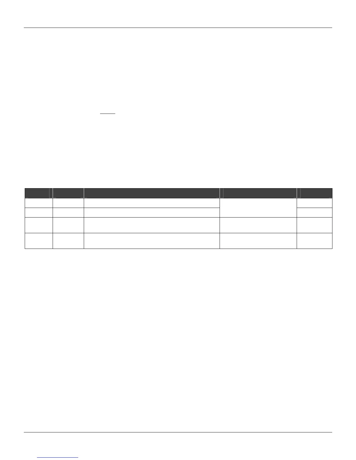
TYPE MNEM DESCRIPTION RANGE DEFAULT
I LIA Input A (to be totalized) 0
I LIB Input B (clears totalizer)
Addresses
0 to 170/225 to 240
0
R A-TU Totalization value in volume units or mass units,
corresponding to one counting unit.
0 to 10 E 37 1.0000
R AMFL Flow rate corresponding to 100% at input A, in volume or
mass units (the same units used in ATU) per second.
0 to 10 E 37 10.000
Number of Bytes per Type of Parameter: A = 8 C = 0 L = 4