MAINTENANCE, TECHNICAL SPECIFICATIONS, MOUNTING TEMPLATES 3 - 7
Scanner Signal Descriptions
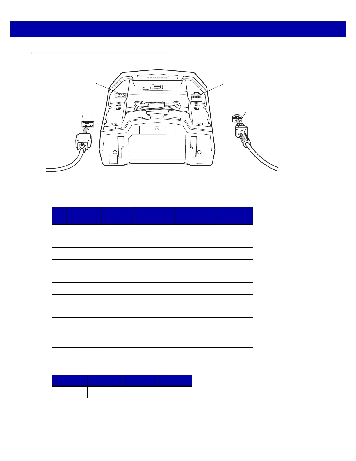
Figure 3-1
Cable Pinouts
The signal descriptions in Table 3-3 apply to the connectors on the scanner and are for reference only.
Pin
4
Pin
1
Host Port
USB Auxiliary
Scanner Port
Pin
10
Pin
1
Table 3-3
Scanner/Host Signal Pin-outs
Pin IBM RS-232
Keyboard
Wedge
USB Download
1 Reserved Reserved Reserved Jump to Pin 6 Reserved
2 +5v +5v +5v +5v +5v
3 Ground Ground Ground Ground Ground
4 IBM_A(+) TxD KeyClock Reserved TxD
5 Reserved RxD TermData D + Reserved
6 IBM_B(-) RTS KeyData Jump to Pin 1 RxD
7 Reserved CTS TermClock D - Reserved
8 Reserved Reserved Reserved Reserved Reserved
9 Passive
Detect
Passive
Detect
Passive
Detect
Passive
Detect
Reserved
10 +12v +12v +12v +12v Reserved
Table 3-4
USB Auxiliary Scanner Port Pinouts
Pin 1 Pin 2 Pin 3 Pin 4
VCC D- D+ GND