1 - 4 DS7708 2D Vertical Slot Scanner Product Reference Guide
Setting Up the Scanner
Power Options
The DS7708 does not have an on/off switch. It is powered via the host through the host cable and is ready to
scan when connected to a host.
•
When an auxiliary scanner is not connected: If an auxiliary scanner is not connected, the DS7708
requires 5VDC from the host. If the host cannot provide 5VDC, or cannot provide sufficient power (for
example, RS-232 or Keyboard Wedge hosts) then an external 5VDC power supply is required.
•
When an auxiliary scanner is connected: If an auxiliary scanner is connected, the DS7708 requires
12VDC from the host. If the host cannot provide 12VDC, or cannot provide sufficient power (for example,
USB Series A type connector, or RS-232) then a cable with a 12VDC power port and external 12VDC
power supply is required.
When the scanner receives power, the green LED lights and three short high beeps sound, indicating that the
scanner is op
erational.
Ports
Host Port. A 10-pin RS-45 type connector is provided to connect various host interface cables.
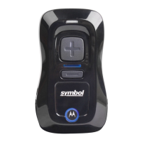
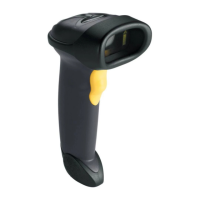
Auxiliary (Hand-held) Scanner Port. A Series A typ
e USB connector is provided to connect an auxiliary
scanner, such as the DS4308. The auxiliary scanner’s host interface is automatically set to match the
DS7708 host interface.
Connecting the Host and/or Auxiliary Scanner Cable
Different hosts require different cables. The connectors illustrated in each host chapter are examples only.
Connectors may be different from those illustrated, but the steps to connect the scanner are the same. See
each individual host interface chapter for interface specific connections.
The back cover must be removed prior to connecting cables (see Removing and Replacing the Back Cover on
page 1-5).
NOTE For detailed connection information, see the applicable host interface chapter.