11
910
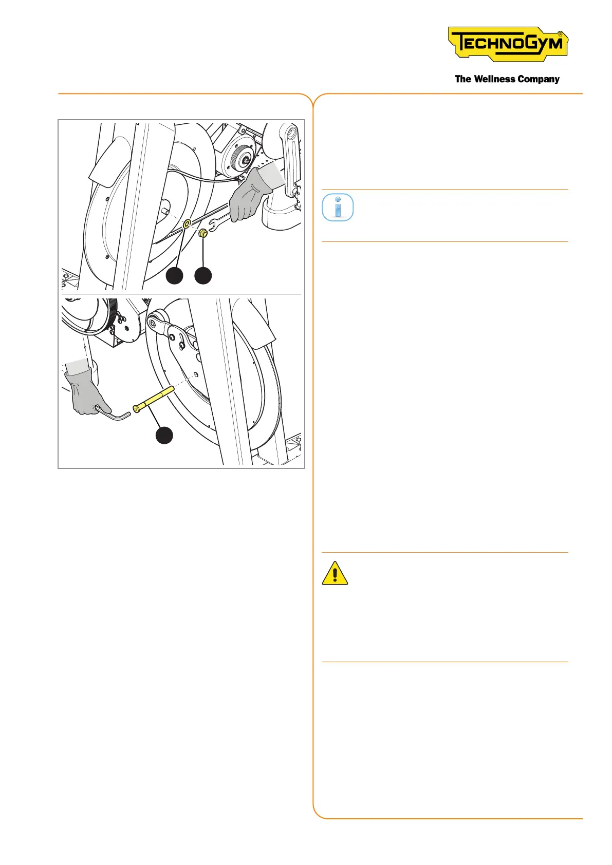
Figure 165
10. Insert the screw (11) to remove the cen-
tring pin. Insert the washer (10) and tight-
en the nut and the screw with a 19 mm
wrench and a 6 mm Allen wrench..
Work from both sides counteracting the
wrenches.
Finishingtheitembackontothebikebyfollow-
ing the aforementioned procedure in the reverse or-
der (steps 1 - 4).
ATTENTION: If the Group Cycle has the
Wa Sensor ID, follow the procedure
described in paragraph “6.7 procedure
to follow if it is necessary to remove the
plate on which the Wa Sensor ID is
xed”, point 3.
Tighten the belt as indicated in “11.5.1 Tighten-
ing the transmission belt”.
Calibrate the brake as indicated in “6.5 Brake
calibration”.
New Group Cycle (D92):
Technical Service Guide - Rev. 5.1
Document uncontrolled when printed
Page 165