15 14
Figure 162
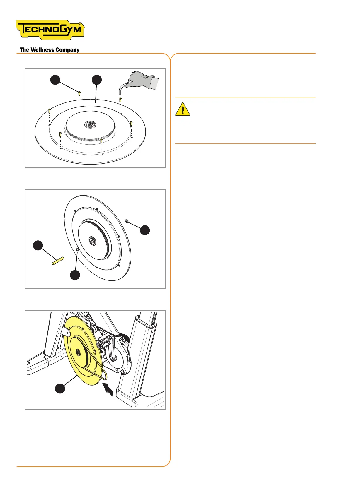
7. Replace the aluminium disc (14) by un-
screwing the screws (15) with a 3 mm Al-
len wrench.
ATTENTION: When reing the screws
(15), apply Loctite 243 on them and
tighten them with a torque equal to 5
Nm (3.69 lbf-ft).
16
13
13
Figure 163
8. Use a Ø 12 x 95 mm lock pin (16) and po-
sition the spacers (13).
12
Figure 164
9. Position the transmission belt and - where
applicable - the generator belt, then t the
ywheel (12) in its seat.
New Group Cycle (D92):
Technical Service Guide - Rev. 5.1
Document uncontrolled when printed
Page 164