8
Figure 180
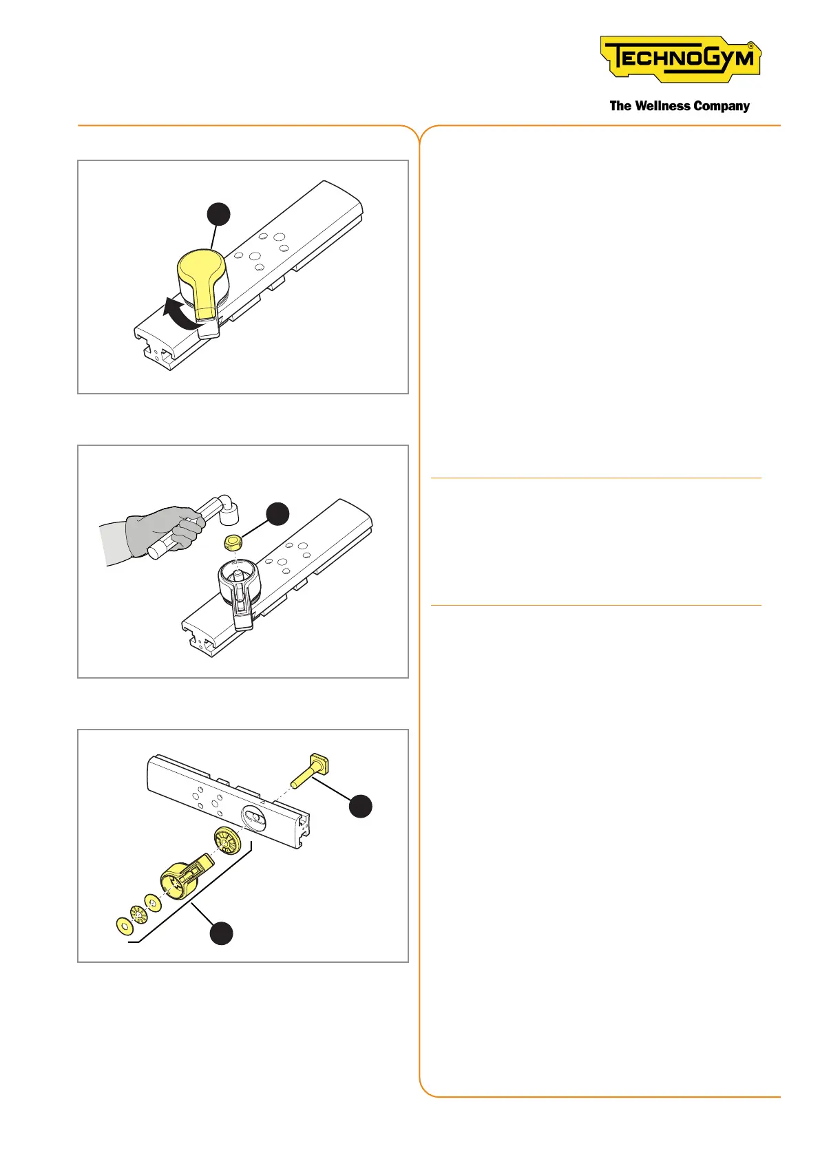
8. Remove the cover (8).
9
Figure 181
9. Remove the nut (9) with a 13 mm tubular
box wrench.
Every time you remove the self-locking nut
(9) from the machine: it’s requested to re-
place the self-locking nut with the new one.
The self-locking nut must be tightened with
a torque wrench set to 3.9 Nm (2,88 lbf- ft).
10
10
Figure 182
10. Remove the quick-release lever (10).
To reassemble the handlebar’s horizontal slider and
t back on the bike, follow the aforementioned in-
structions in the reverse order.
New Group Cycle (D92):
Technical Service Guide - Rev. 5.1
Document uncontrolled when printed
Page 173