Figure 36
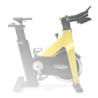
3. Check that the knob is in a hori-
zontal position (must be the zero
position).
4. If the knob is not in a horizontal
position, move it so it is in this
position. Keep the knob station-
ary with one hand and adjust the
self-locking nut (3) that rests on
the black plastic spacer (4).
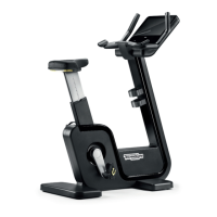
5
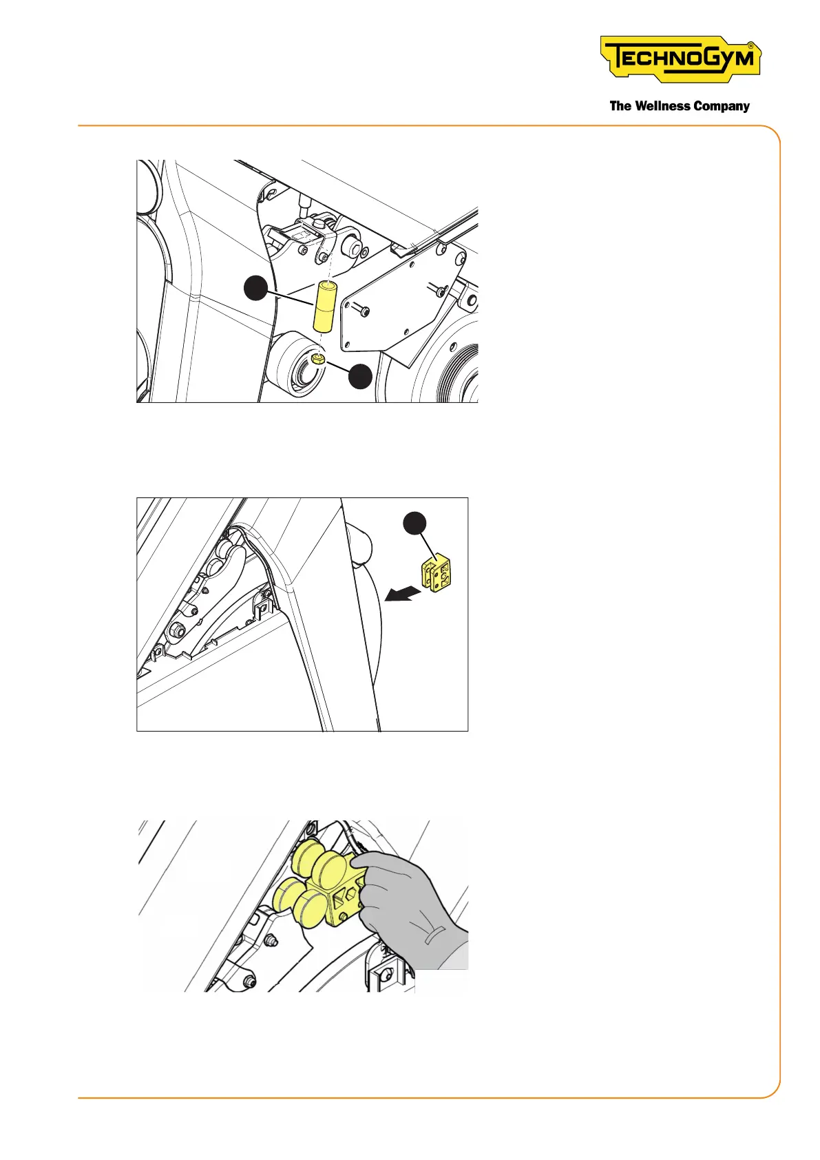
Figure 37
5. Place the correct template (5) on
the aluminium disc and check
that the magnets on the brake
come into contact with the tem-
plate, as shown in the following
gure.
Figure 38
New Group Cycle (D92):
Technical Service Guide - Rev. 5.1
Document uncontrolled when printed
Page 63