3. Connect two more low-noise cables to the front of the Model 5951, where the input and output to
the device are located.
4. Connect the dark box to the cable grounds only. If this is not possible, connect a #18 AWG wire
between the dark box and the white banana jack on the back of the Model 595.
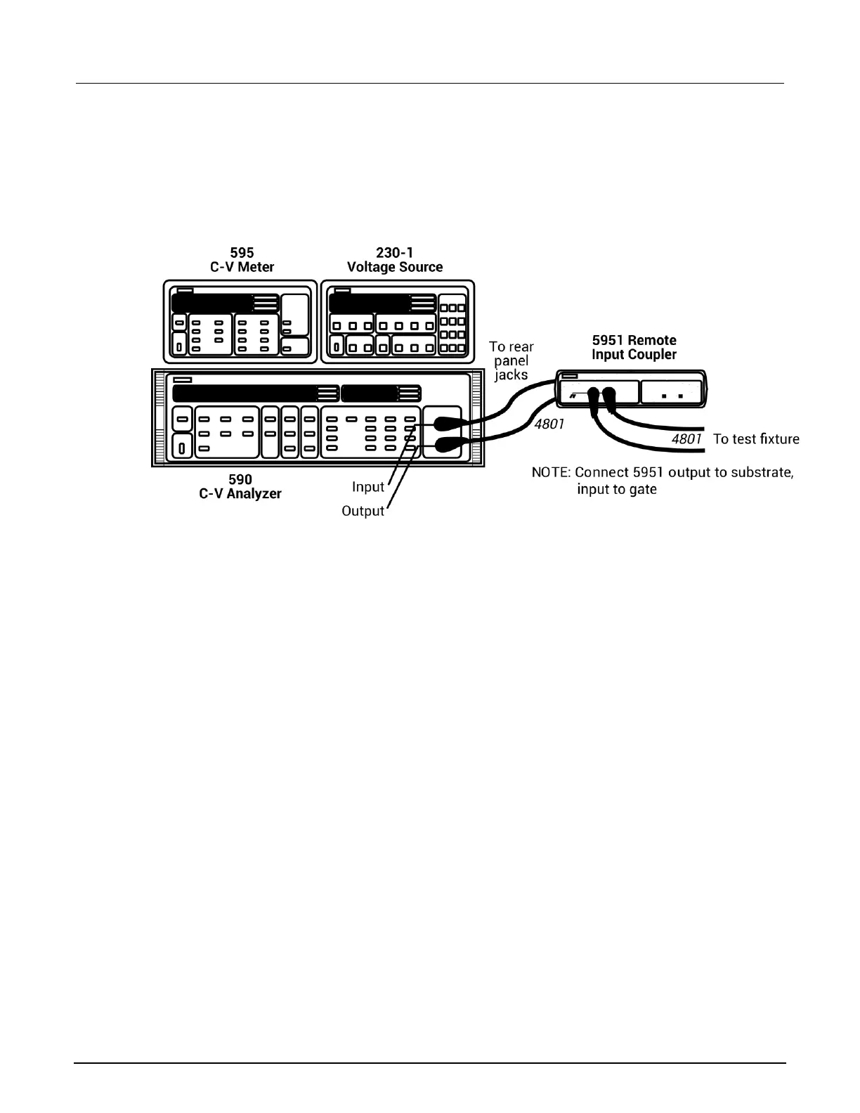
Figure 82: System 82 C-V system front-panel connections
Rear-panel connections
The rear-panel connections diagram below shows the rest of the main cabling configuration.
To make rear-panel connections:
1. Use a Model 4801 cable to connect the METER INPUT on the back of the Model 595 to the TO
595 INPUT on the Model 5951.
2. Use a Model 7051-2 BNC cable to connect the METER COMPLETE port on the back of the
Model 595 to the TRIGGER INPUT on the back of the Model 590.
3. Use a Model 7051-2 cable and connect the OUTPUT HI on the back of the Model 230-1 to the
BIAS INPUT on the back of the Model 590.
4. Use a Model 7051-2 BNC cable to connect the OUTPUT LO on the back of the Model 230-1 to
the VOLTAGE SOURCE OUTPUT on the back of the Model 595.

 Loading...


