Typical CVU matrix card connections
In your project, you can automate the use of a CVU and other instrumentation using a switching
matrix and actions to control the switching. When the project is run, the switching matrix automatically
makes the required instrument connections for each test in the project.
The next figures show typical connections for a switch system using a Series 700 Switching System
with the 7174A Matrix Card installed.
You can also use the 7072 Matrix Card for C-V testing. If you are using the 7072, you must use rows
G and H and local (2-wire) sensing.
The SMA cables and adapters shown in the following figures are supplied with the CVU or the
4200-CVU-PROBER-KIT. The triaxial and BNC cables are not supplied. The prober kit includes two
types of BNC-to-triaxial adapters that connect directly to the rows of the matrix. The 7078-TRX-BNC
has the guard connected to the inner shield of the adapter. The 7078-TRX-GND has the guard
disconnected.
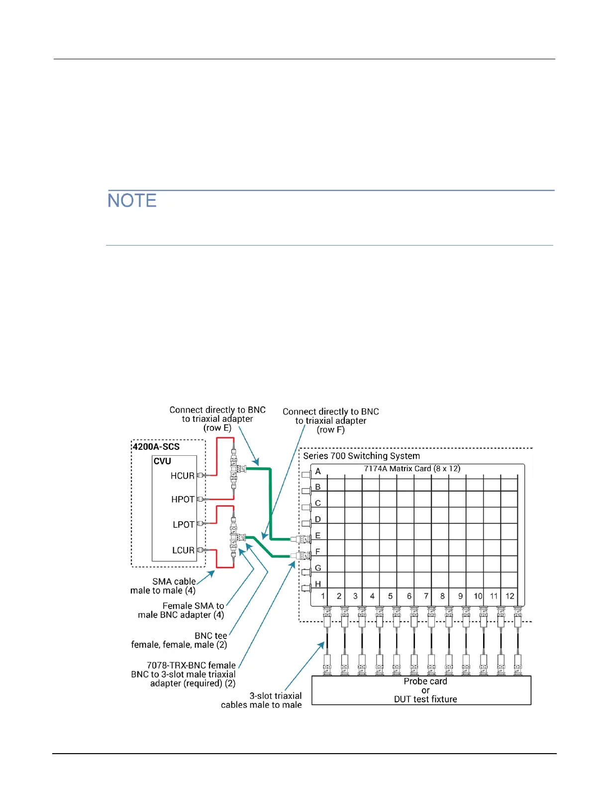
This figure shows connections for local (2-wire) sensing with the CVU connected to rows E and F of
the matrix. This is the connection scheme for the cap-iv-cv-matrix project. For details, see
“cap-iv-cv-matrix” in the Model 4200A-SCS Capacitance-Voltage Unit (CVU) User's Manual.
Figure 8: Test connections for a switch matrix - local (2-wire) sensing

 Loading...


