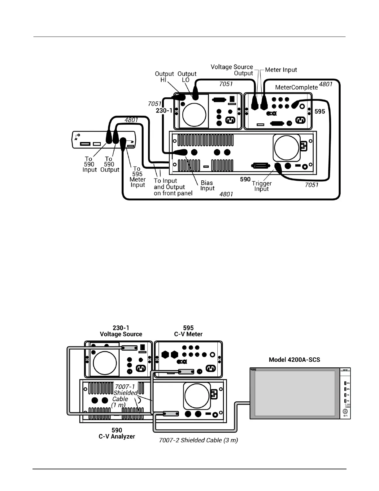
Figure 83: System 82 C-V system rear-panel connections
Make power and GPIB connections
To attach the power and GPIB connections:
1. Use the ribbon cable to connect the DIGITAL I / O PORT on the back of the Model 230-1 to the
TO 230-1 DIGITAL I / O on the back of the Model 5951.
2. Use the power cables to plug in the units.
3. The following figure shows the connections for the GPIB bus cables. Use the GPIB bus cables
and connect the Model 590, the Model 595, and the Model 230-1 to the 4200A-SCS through the
GPIB card.
Figure 84: System 82 IEEE-488 connections
 Loading...


