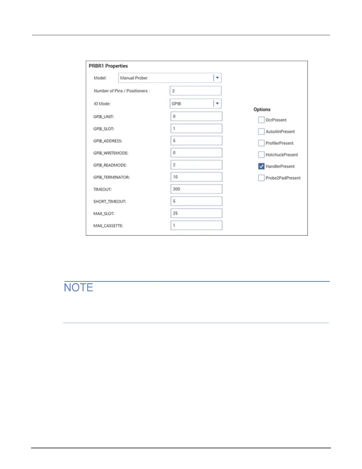
Figure 24: Probe station properties
5. From the Model list, select the prober.
6. Enter the Number of Pins / Positioners.
7. Select the options that are appropriate for your prober.
The number of pins defined in the probe station properties determines the pins that are available to
assign to a switch matrix card column. Make sure the number of pins assigned is appropriate for
your system.
Step 3. Add switching system mainframe
To add a switching system mainframe:
1. Select Add External Instrument.
2. Select the Keithley 707/707A/707B Switching Matrix or Keithley 708/708A/708B Switching
Matrix.
3. Select OK.
4. In the System Configuration list, select the switching matrix. The properties are displayed. The
following figure shows the properties for the 707/707A/707B. If the 708/708A/708B mainframe is
selected, there is only one switch card slot.

 Loading...


