12. Click Next.
13. Select the die position. Optionally, select Show Partial Die.
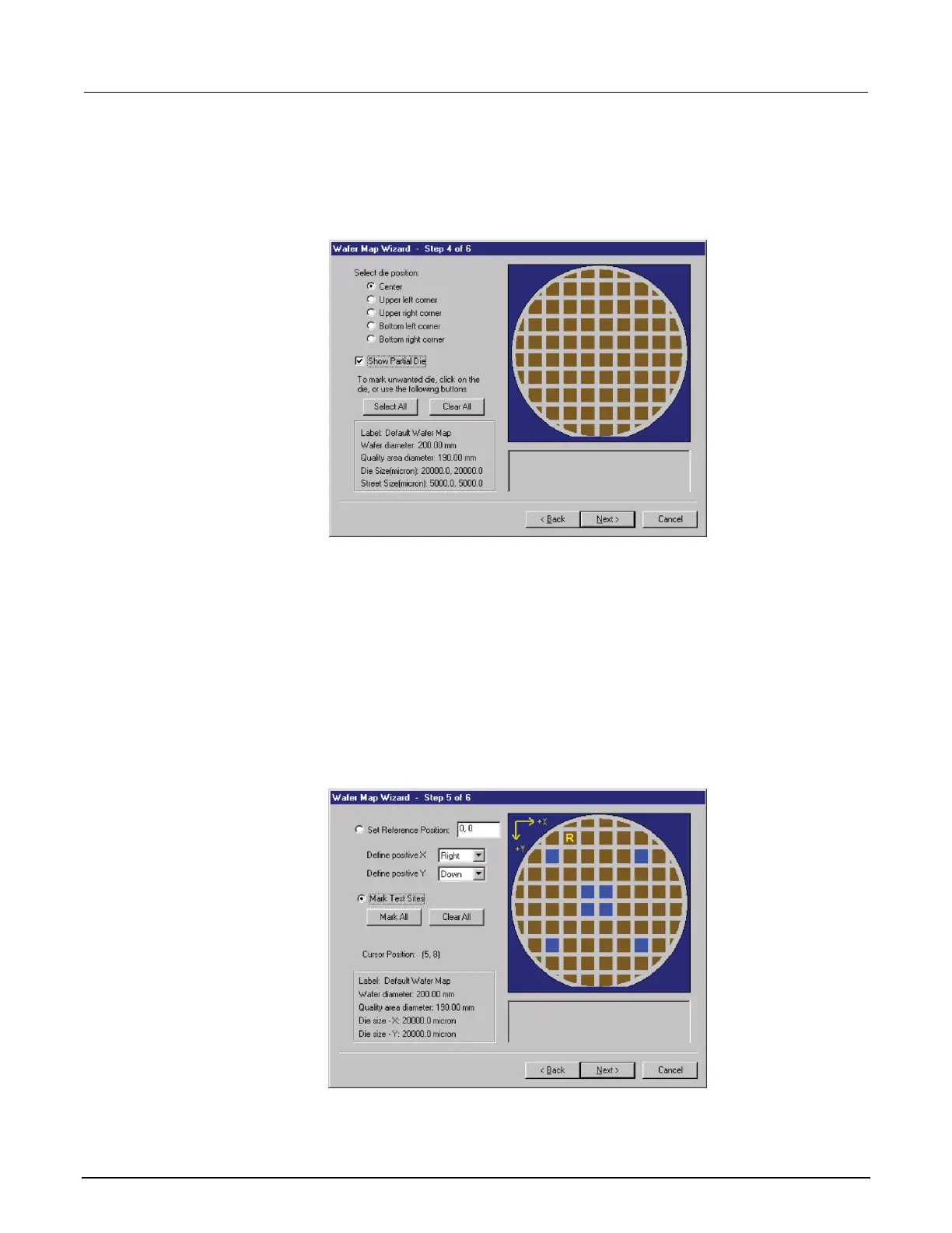
Figure 254: Step 4: Wafer Map Wizard
14. Click Next.
15. Set the reference position.
16. Enter positive X and Y value directions (this defines the coordinate). For example, setting Define
Positive X: Right, and Define Positive Y: Up would define the coordinate as Quadrant I, while
setting Define Positive X: Right, and Define Positive Y: Down would define the coordinate as
Quadrant IV.
17. Select Mark Test Sites. You can drag to select multiple sites.
Figure 255: Step 5: Wafer Map Wizard

 Loading...


