X35 console System Components
1.9
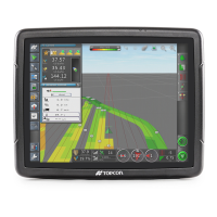
Figure 1.18 - Case Drain Pressure Switch
Casepress_newStyule.jpg
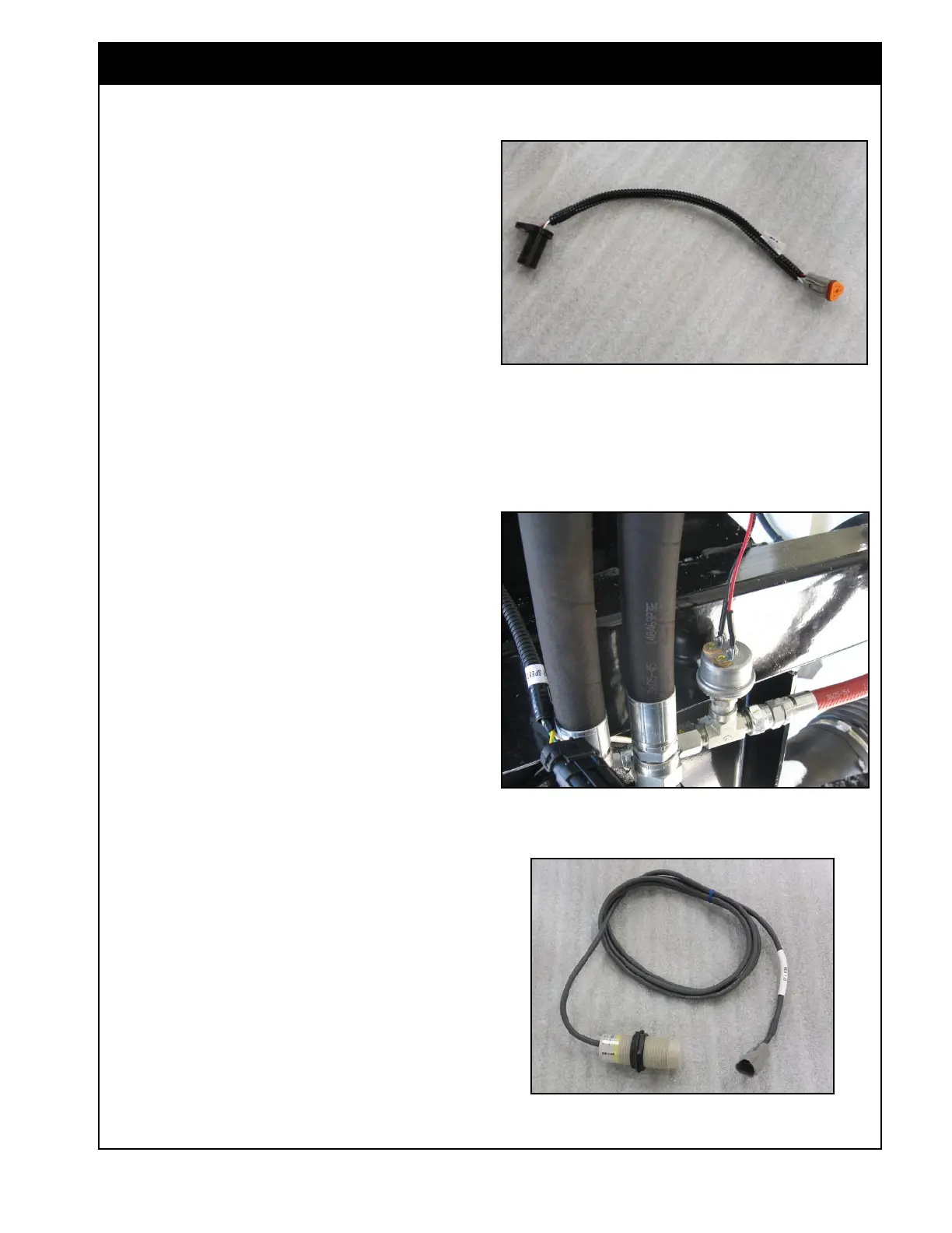
Figure 1.17 - Speed Sensor
SpeedSensor.jpg
1.6 Speed Sensors
There are speed sensors in several locations on the
air seeder. These include fan speed, ground speed,
and metering auger speed. All of these sensors are
proximity style and send a signal to the ECU.
1. the fan speed sensor picks up from a target
bolt on the fan hub (one pulse per revolution).
2. the ground speed sensor is located on the rear
left wheel mount or drive. It picks up a signal
from a sprocket.
3. the metering auger sensors are on the
metering auger housing and pick up the signal
from a sprocket on the metering auger shaft
(32 pulses per revolution for 7000AS, and 16
pulses per revolution for 6000AS).
1.7 Case Drain Pressure Switch
A pressure switch (Figure 1.18) is installed in the
fan hydraulic motor case drain line. This controls
an alarm that will activate if the case drain
pressure is too high (greater than 65psi). High
case drain pressure may result in damage to the
hydraulic motor.
1.8 Low Bin Level Sensors
Each air seeder compartment contains a single bin
level sensor installed near the bottom. The sensor
will trigger an alarm when there is no product in
front of it.
The X35 provides a
calculated (not actual) method
of reporting the product remaining in the tank.
This value is based on the metering auger output
in relation to the product amount entered at time
of fill. This value should be used as reference
only.
Figure 1.19 - Bin Level Sensor
BinSensor.tif