Using 3D Guidance in the Field 5
Selecting a 3D line
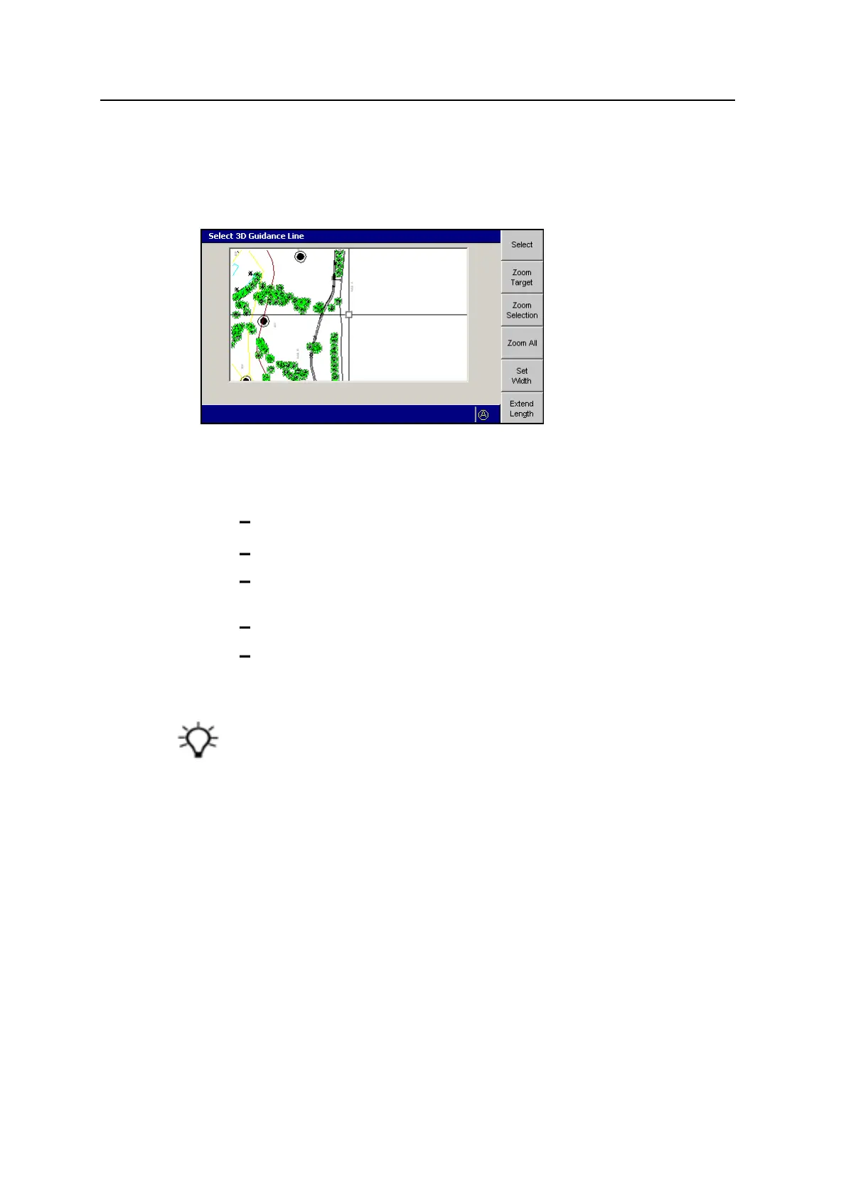
If the loaded design is a 3D lines design, which may specify multiple design
surfaces, the Select 3D Guidance Line dialog appears:
To select a 3D line for guidance:
1. From the Select 3D Guidance Line dialog, move the cross-hairs to the 3D line
that you require. Use any of the following tools to move the cross-hairs:
To move the cross-hairs around the screen, use the arrow keys.
To zoom the current view in and out, press + or -.
To resize the current view to the immediate area around the cross-hairs,
press Zoom Target.
To view all of the linework, press Zoom All.
To view the extents of the selected 3D line, press Zoom Selection.
All linework for the design, including the site map and any avoidance zones, is
shown in this dialog. You can only select a line that is a 3D line.
Tip – If several lines are grouped closely, press Zoom Target to zoom in for easier
selection. Alternatively, move the cross-hairs to an area where the lines are more easily
seen. To move the cross-hairs large distances across the screen, zoom out and then
hold down an arrow key. This lets you move rapidly across the design.
2. To select the 3D line for horizontal and vertical guidance, press Select. The
line closest to the center of the cross-hairs is selected. The selected 3D line
appears as a thick red line.
GCS900 Grade Control System for Excavators Operator's Manual 119