Using theControl Box and Lightbars 2
Machine type Plan View icon Profile View Icon
Excavator with variable
angle boom
If the machine you are operating is not shown, contact your site supervisor.
Guidance settings
To display guidance settings, the system uses a variety of icons to identify the
sensors being used to generate guidance information, and text to display numerical
values.
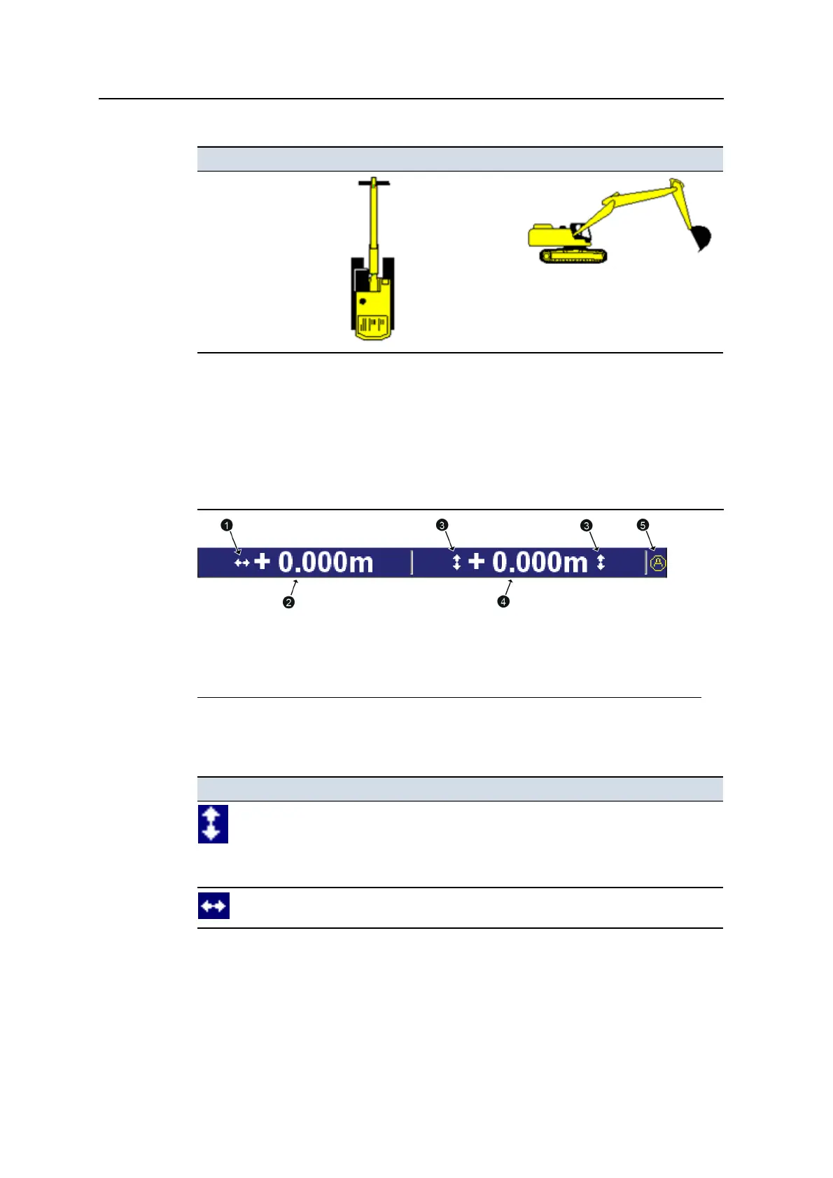
1
3D horizontal guidance
icon
2
Horizontal offset
3
Elevation guidance
icons
4
Vertical offset
5
Mapping/Recording icon -
set to Auto
Figure 2.2 Example guidance setting area for a 3D excavator system
Guidance setting icon Meaning
Elevation guidance is available.
3D vertical guidance information is being generated.
For 2D systems, the system has been benched, but the benchmark
elevation has not been referenced to a laser plane.
3D horizontal guidance information is being generated.
Table 2.2 — Guidance setting icons used by the system
GCS900 Grade Control System for Excavators Operator's Manual 35