2 Using the Control Box and Lightbars
If there are more than three text items selected for display, then the text
information area appears down the right side of the screen.
If there is no text information configured for that view, the text information
area does not appear.
l The guidance settings status bar 3. The guidance settings status bar displays
the current sensors and guidance settings being used to generate guidance
information. For more information, see Guidance settings, page 35.
Machine icons
The system uses a variety of icons to identify the machine in the guidance views:
l The bucket icon provides information on the bucket slope in cross-section view.
l The cutting edge tip in an icon corresponds exactly to the cutting edge tip of the
machine.
l As you move the machine and bucket, the icon mimics the movements on the
screen.
l The red square on the bucket indicates the horizontal guidance point (the
bucket focus), if applicable. The green line on the bucket indicates the vertical
guidance point(s).
Note – The position of symbols for other parts, in particular the tracks/wheels or
rear corners, are approximate and for indication only.
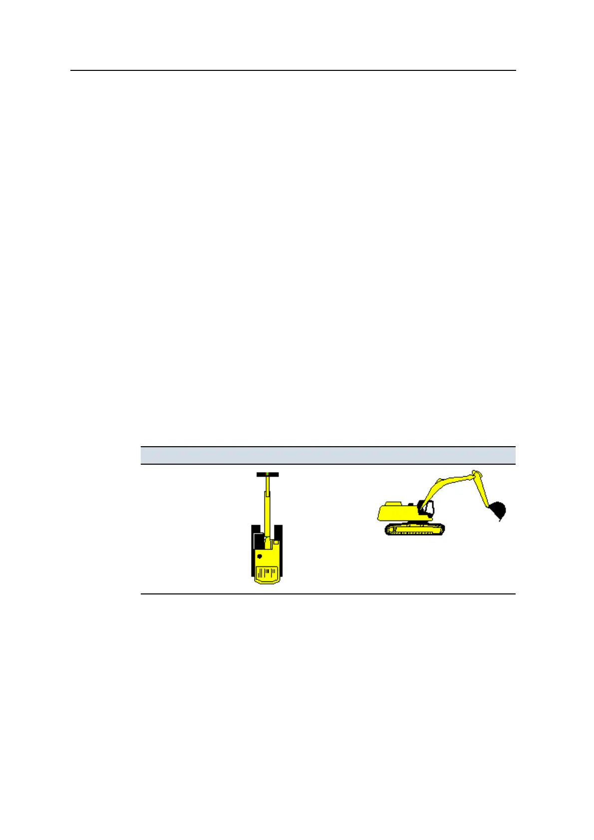
Machine type Plan View icon Profile View Icon
Excavator
Table 2.1 — Machine type and icon
34 GCS900 Grade Control System for Excavators Operator's Manual